

Join Renato Nogueira and ...... on this year CINDE
A pipelines main vulnerability is located at the welded joints connecting sections of the line. The welding process introduces heat affected zones that lead to structural changes in the metal that weaken the part in the weld area, the fatigue resistance, is lowered and the overall strength and toughness can be affected.
Additional failure mechanisms can be introduced during service, these can include;
- Temperature fluctuations
- External corrosion from the environment or water held in lagging
- Internal flow erosion
- High pressure cycling
- System vibration
- Mechanical damage
Methods of mitigating these issues are available but the weld should always be considered a point of weakness and be regularly inspected to monitor its condition.

Figure 1 – Pipeline welding and on site image of pipework
Inspection Methods
Multiple inspection methods exist to assess pipeline welds, these include surface methods such as Visual, Magnetic Particle, Dye Penetrant and Eddy Current inspection, these only inform the inspector on the condition of the surface and slight subsurface of the weld. Full volumetric inspection requires Ultrasonic methods (UT) or Radiography (RAD).
UT has many advantages over RAD, the main ones being.
- UT produces no radiation hazard and can be carried out alongside other personnel; this is a safer process than radiography and means the site does not need to be cleared of workers for the inspection to take place
- UT is sensitive to small defects, cracking defects and planar lack of fusion defects making it a great application for thinner pipework but is also applicable for thicker materials.

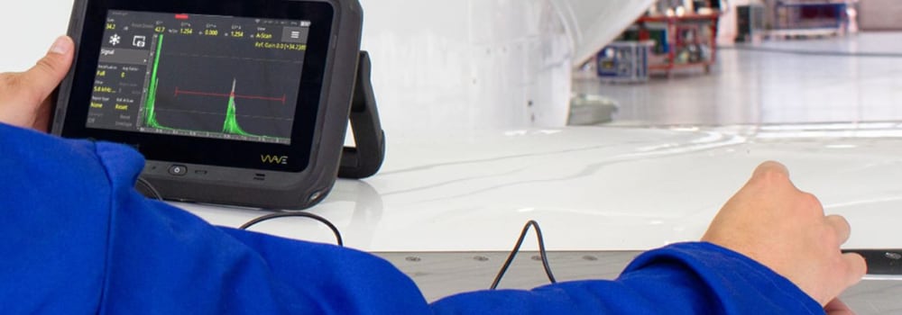
Figure 2 – Ultrasonic inspection of Butt welds on pipe sections
Inspection Challenges of Circumferential Butt Welds
The most common circumferential weld geometry is pipe to pipe, both sides are the same material and same thickness, but this is not always the case, a pipe section can be welded to fittings such as bends, reducers, tees, and flanges which can be different thicknesses, made of cast materials and have attachments restricting access for inspection. All of these are points to consider when choosing the correct ultrasonic method for the inspection.
Figure 3 – Examples of Butt weld configurations that can be encountered
Types of Ultrasonic Inspection
Conventional Ultrasonic Inspection (UT)
UT utilizes single or dual crystal transducers in single beam configurations to interrogate a weld. Transducers are set to produce specific known angles in the material (usually 0°, 45°, 60° and 70°, but other angles can be used) manual ‘scanning’ or movement of the transducer on the surface ensures coverage of the weld, return signals are interpreted by the inspector to detect and size defects.
See our Butt Weld Inspection application note (pdf, 2.4mb) for more information
Figure 4 – Example of how conventional UT interacts and displays a defect
Phased Array (PA)
A PA inspection is carried out using a transducer containing multiple individual elements in an array. These elements are pulsed individually or in groups to create a beam that can be directed and focused depending on the requirements of the inspection. PA inspection can inspect full weld volumes in a single sweep or interrogate specific areas of a weld and produces a recorded data file with views that can be manipulated to aid interpretation.
See our PAUT Butt Weld Inspection application note (pdf, 2.8mb) for more information.
Figure 5 – Examples of how a PA S-Scan interacts with defects
Full Matrix Capture / Total Focusing Method (FMC/TFM)
FMC is a form of data capture utilizing PA transducers, individual elements are pulsed, and A-Scan data is recorded by each of the remaining elements, this process is repeated for each element in turn creating a large set of data. TFM is a method of processing and displaying an FMC data set, an area of interest is chosen as a resolution set. FMC takes each pixel in this area and averages the total number of A-Scans for this pixel, creating a new A-Scan. As this is the average of 100s or 1000s of A-Scans, it reduces noise and is focused on this pixel. Repeating this for each pixel creates a view where the scan is focused at every pixel in the area.
See our TFM/TFMi Butt Weld Inspection application note (pdf, 4.4mb) for more information.
Figure 6 – example of defect detection display of PA (Left) and TFM (Right)
Time of Flight Diffraction (TOFD)
TOFD utilizes two transducers set apart and facing each other in a ‘pitch-catch’ formation. One transducer sends a pulse into the material and the other transducer receives. Instead of using reflections from defects and displaying results as depth of reflection or beam path, TOFD detects ‘tip diffraction signals’ which are much weaker and displays results in time of flight. This gives a technique that has a high accuracy to defect depth and through wall height and is often used in the calculations for fracture mechanics.
See our TOFD Inspection of Butt Welds application note (pdf, 2.7mb) for more information.
Figure 7 – ToFD scan showing defect signals
For more information please get in touch.
Please contact our Applications Team if you have any questions. You can also find more solutions on our website.
Stay up to date with our latest content. Sign up here to get our blogs delivered straight to your inbox.
News Filter...
The latest news from Sonatest direct to your inbox.
Tags

