

What is Pipeline Corrosion and Erosion?
Pipelines are critical infrastructure assets. However, corrosion poses significant risks to their integrity. Ultrasonic testing (UT), particularly phased array ultrasonic testing (PAUT), is pivotal for corrosion mapping.
Flanges play a crucial role in maintaining the integrity and safety of pipeline systems, providing secure connections between pipes, valves, tees, and other fittings.
Valves are often chosen over welded joints for the ease of maintenance, a spool or valve can easily be replaced by simply disconnecting the flange and swapping out the defective part with a new one. This saves downtime on the overall system where cutting and welding a replacement can take days in some cases.

Fig. 1 - Flange connections on offshore pipeline
Inspection Methods
The inspection of flanges is critical to the safety and integrity of the pipeline or vessel they are attached to. Traditionally, the simplest way to identify an issue with a flange face is to observe a leak or “split” the joint to visually inspect the face when the line is off for maintenance.
There are obvious issues with these methods, observing a leak means the flange has already failed and containment is lost, this is too late. Conducting visuals require the system to be offline and the flange to be opened, this involves removing bolts and lowering one or both sides of the connection to see the face. This is time consuming and expensive; some pipelines may include hundreds of connections.
Ultrasonic methods can be used to inspect flange face condition without the need to open the flange or even empty the line! This enables the user to inspect the flange face without forcing the shutdown of the asset and still get the information on the condition of the flange face. Ultrasonic inspection is often the preferred choice to ascertain flange face condition.
Inspection Challenges
Ultrasonic inspection of flanges, while effective, comes with several challenges.
- Geometry – Flanges come in various shapes and thickness combinations, providing challenges for probe contact on the various inspection surfaces, wedge contouring and scanners can be needed to ensure consistent probe contact
- Bolt restrictions – both the bolts and bolt holes cause test restrictions, both blocking 100% coverage from a scan and restricting probe position on some inspection surfaces
- Inspection surface access – lagging and proximity to adjacent pipework can restrict access to certain scanning surfaces, causing restricted inspections
Inspection surfaces
Flange face inspection can be carried out from three main surfaces, each with their own pros and cons.
- Outer Face – The outer face is often the easiest surface to access, giving 360° contact with a good view of the inner bore of the flange, however the curved surface can lead to an unstable probe position and the bolt holes prevent a 100% scan coverage of the inspection area

Fig. 2 - Outer face scan position
- Bolted Face – The bolted face is a good flat surface where the probe can sit easily and have a good scan view of the flange face for inspection, however the bolts prevent 100% scan coverage, in some cases in high pressure lines the number of bolts can prevent the probe from access all together

Fig. 3 - Bolted face scan position
- Pipe / Tapered section – The pipe section of the flange provides the user with a 360° surface for scanning with good scanning conditions to observe the flange face, however this area is the most difficult to access and requires the bolts to give enough clearance for a probe to carry out the scan.

Fig. 4 - Pipe / Tapered section scan position
Ultrasonic Solutions
Conventional Ultrasonic Inspection (UT)
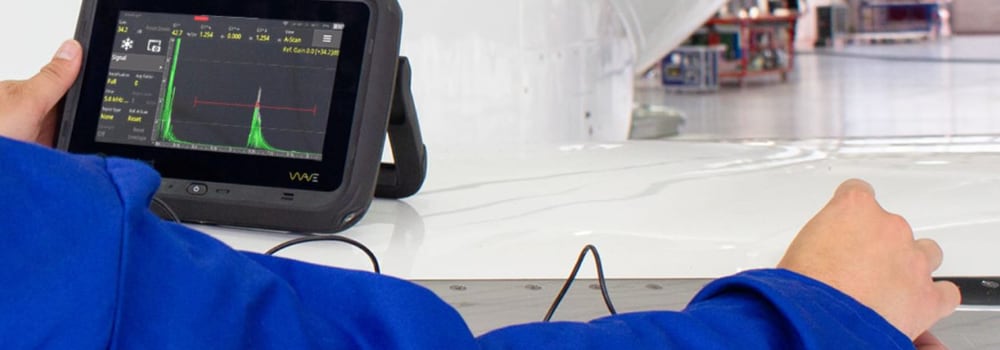
Conventional Ultrasonic Testing (UT) inspection is an invaluable tool for quickly identifying flange face defects and inner bore corrosion in situ on operational assets. Historically, this method has relied heavily on the expertise of operators to detect defect signals amidst often complex geometries, making it a highly skilled inspection process.
The Sonatest Wave enhances this process by providing inspectors with an interactive scan plan and the ability to import CAD DXF files. This functionality helps users distinguish between geometric and defect signals more effectively. Additionally, inspectors can save screenshots of the scan plan and defect signals for further analysis and documentation.

Fig. 5 - Conventional UT using the Wave
Phased Array Inspection (PA)
Phased Array (PA) inspection has revolutionized flange face inspection by enabling the capture of detailed scan images of defects. This method allows for a comprehensive view of the flange face without the need to disassemble the joints. By detecting and recording defects, asset owners can monitor these issues over time, facilitating planned maintenance and reducing the risk of unplanned shutdowns due to failures.
As illustrated in Figures 2-4, PA inspection can be adapted to various flange geometries. This flexibility, combined with the extensive data it provides, underscores the significant value of PA inspection in maintaining flange integrity.

Fig. 6 - Phased Array scan data from a flange face
Total Focusing Method (TFM)
Total Focusing Method Inspection is a relatively new technique in the field of Non-Destructive Testing (NDT). It offers the ability to target critical areas of a flange face and provide data focused on the region of interest (ROI), addressing many challenges encountered with PA inspection on complex geometries. The higher resolution of the images obtained through TFM allows for more accurate defect sizing, leading to greater precision in asset management calculations.
TFM can be used alongside PA on the Veo3, enhancing the overall inspection process. This dual approach enables the collection of more comprehensive data from each inspection, resulting in more detailed reports for clients.
 corrosion defect (middle) and defect image (right)")
Fig. 7 - TFM images showing no defect (left) corrosion defect (middle) and defect image (right)
Conclusion:
The inspection of flanges is a critical aspect of maintaining the safety and integrity of pipeline systems. While traditional methods such as visual inspections and leak observations have their limitations, advanced ultrasonic techniques offer significant advantages. Ultrasonic inspection methods, including Conventional UT, PA, and TFM, provide detailed and accurate assessments of flange conditions without the need for system shutdowns. These methods address various challenges such as geometry, bolt restrictions, and access issues, ensuring comprehensive and reliable inspections. By leveraging these advanced techniques, asset owners can effectively monitor flange integrity, plan maintenance activities, and minimize the risk of unplanned shutdowns, ultimately enhancing the overall efficiency and safety of their operations.
Please contact our Applications Team if you have any questions. You can also find more solutions on our website.
Stay up to date with our latest content. Sign up here to get our blogs delivered straight to your inbox.
News Filter...
The latest news from Sonatest direct to your inbox.
Tags


