

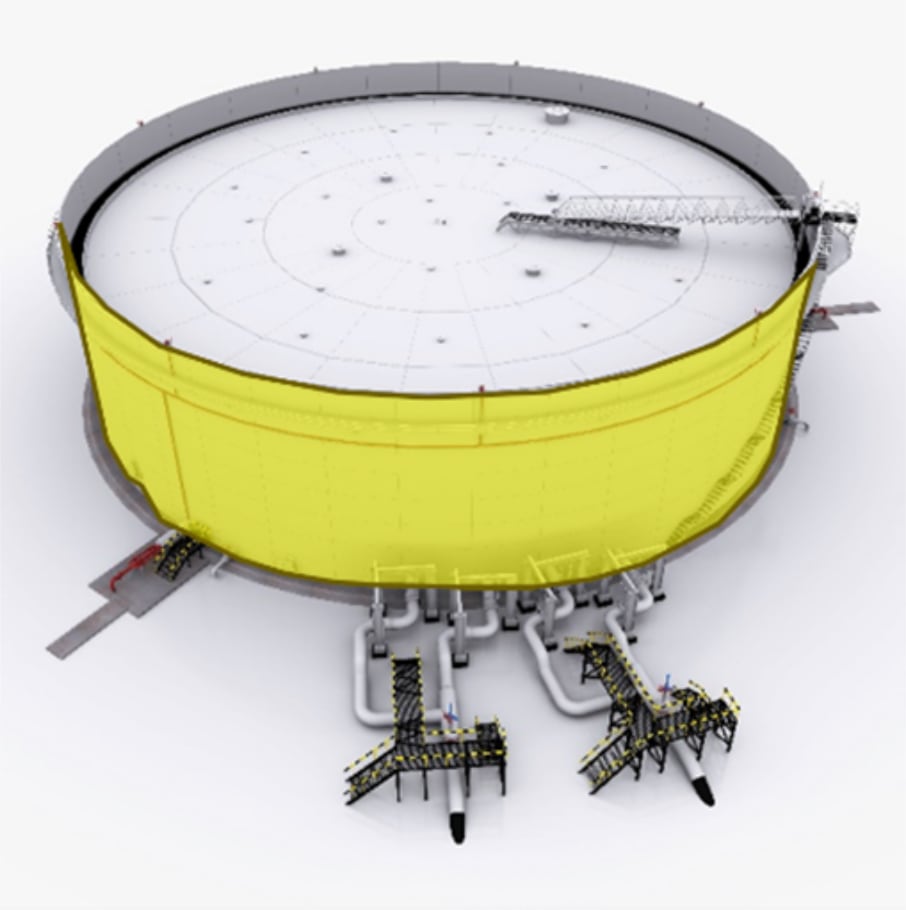
The shell of a storage tank is designed to contain the product, support the roof, and withstand external pressures without buckling.
The strength of the tank shell comes from the following design choices:
- Material type
- Thickness of each course
- Welding type
- Introduction of wind girders
Corrosion, erosion, stress, corrosion cracking of the welds, and more can affect the above points, weaken the overall strength of the tank, and reduce the safe operating conditions of the asset.
In this blog, we will explore the available ultrasonic methods for detecting defects in the plate, welds, and connected pipework on the shell.
Thickness Surveys and T-Logging
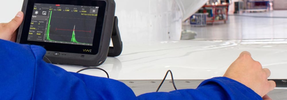
The most basic form of inspection for determining the shell plate thickness is ultrasonic testing (UT). Conducting the inspection with thickness gauges or flaw detectors, the inspector uses a UT transducer on the plate surface to obtain a live thickness reading from the contact point.
Thickness surveys are a simple and repeatable method of monitoring the condition of your tank shell.
Uses:
- Spot readings should be taken at locations around the circumference of the tank, covering the full height with readings on every course and the top angle
- Readings on corrosion patches to determine the hoop stress calculation results
- Spot readings on attachment reinforcement plates, repair patches and pipelines
For further information on our equipment and application notes, follow these links:
Ultrasonic Flaw Detectors, Thickness Gauges, App Notes
Corrosion Mapping
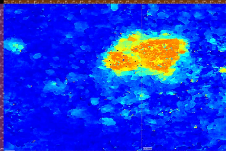
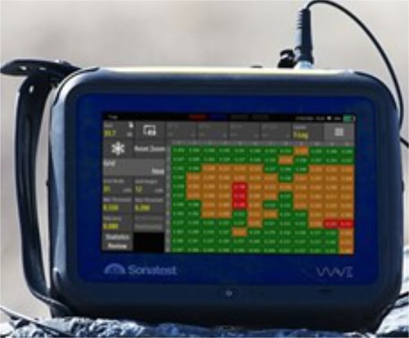
When detailed coverage of large plate areas is required, UT/ phased array (PA) corrosion mapping offers an ideal solution.
Conducted manually in specific areas or automated by scanners that can access areas high up on the tank shell without the need for scaffolding, it is capable of quickly recording thickness data and presenting this information as a visual map that clearly details any wall loss areas by corrosion and pitting.
The data file also presents a permanent record of the condition of the area, and on repeated inspections, the corrosion area corrosion growth during repeated inspections.
Uses:
- Detecting and monitoring for pitting and corrosion patches
- Monitoring the wind and water line for erosion caused by product or floating roof movements
- Establishing baseline condition maps of the shell plates
For further information on our equipment and application notes, follow these links:
Phased Array Equipment, Scanners, App Notes
Weld Inspection
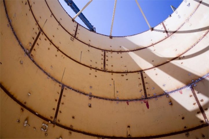
Various types of weld configurations can be found on storage tank shells. Modern tanks primarily use butt welds, while some older generation tanks have lap welded joints or a combination of both. Repair inserts and nozzle welds can also be found on the shell and require inspection.
Shell welds are critical for the safe containment of the stored product. Since the joint between plates is inherently a weak point in any structure, it requires regular inspection to ensure that the welding initially meets the high standards necessary for the tank. Additionally, throughout the tank's life, these inspections help detect developing defects such as cracking and root erosion that can lead to weld failures.
Manual UT, phased array, ToFD, TFM, and TFMiTM are all methods that can be used to inspect welds and detect original welding defects or those that have developed over the tank's life.
Sonatest provides advanced equipment, transducers and scanners to carry out weld inspections in all configurations and situations.
For further information on our equipment and application notes, follow these links:
Phased Array Equipment, Scanners, App Notes
Wind Girders and Top Curb Angle Inspections
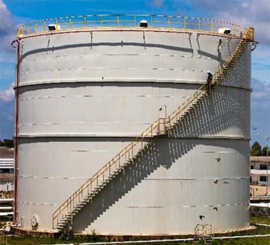
Above-ground cylindrical storage tanks must account for wind gusts that could cause the shell to buckle and fail. To avoid this issue, the top of the shell is equipped with a “top curb angle”; this is an ‘L-Angle’ beam that runs along the highest shell course and acts as a stiffener for the shell.
In larger tanks or in areas with higher wind levels, the top curb angle may not be sufficient to protect the tank from buckling. In these cases, a calculation is made to determine the number and height of additional wind girders.
Both the top curb angle and wind girders can trap water against the shell plates, leading to areas of corrosion. Regular inspections of wall thickness, weld quality, and the condition of the attached shell plates is required. Degradation in any of these areas reduces the tank's capability to withstand high winds.
Sonatest’s conventional UT equipment and T-Log functions are ideal for measuring and recording data on the top curb angle and wind girders.
For further information on our equipment and application notes, follow these links:
UT equipment, Thickness Gauges, App Notes
Corrosion Under Insulation
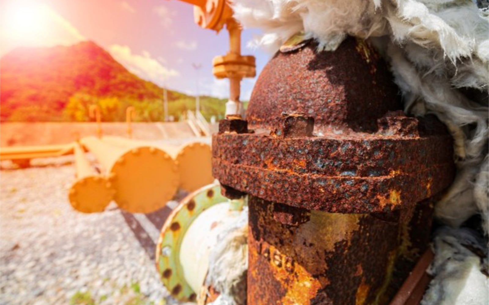
Corrosion under insulation (CUI) occurs when moisture becomes trapped between the insulation and the metal surface of storage tanks or pipes. This moisture can come from various sources, such as condensation, rainwater, or leaks. Factors like compromised or poorly installed insulation and fluctuating temperatures can exacerbate this issue.
CUI is particularly challenging to detect because it exists beneath the insulation, making it an invisible threat until significant damage has occurred or the insulation is removed to reveal the issue. The costs associated with removing insulation from a full tank and reinstalling it are very high, and it may only confirm that the tank is in good condition.
Ultrasonic inspections can be performed from the internal surface of the tank to reveal CUI on the external surface. This can cover 100% or a select percentage of key areas to detect CUI without needing to remove all insulation. This approach can aid in planning for localised insulation removal of specific areas for targeted repairs.
Sonatest provides Conventional UT and advanced PA corrosion mapping equipment to carry out this inspection, saving the asset owner revenue and lost time in the process.
For further information on our equipment and application notes, follow these links:
News Filter...
The latest news from Sonatest direct to your inbox.
Tags


