- Blog
Storage Tank Floor Inspection

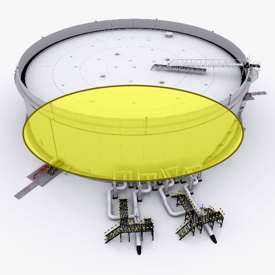
The floor plates of a storage tank are often considered the most critical structural component because of their exposure to the highest operational stresses.
They bear the full weight of the stored material, are most vulnerable to settlement effects, and experience unique corrosion and degradation mechanisms compared to other parts of the tank. Despite their significance, the tank floor is also the most difficult area to inspect, since it remains completely hidden—except for the annular protrusion—until the tank is fully decommissioned and emptied.
Given the safety-critical function of the floor and the infrequency of inspection opportunities, a thorough assessment is crucial whenever access is possible. Consequently, tank floor plates undergo strict inspection protocols, utilising a wide range of non-destructive testing methods to verify structural integrity and meet regulatory standards. These inspection practices form an important part of Construction & Infrastructure NDT, helping operators maintain asset integrity and safety across critical infrastructure.
In this blog, we will explore the role ultrasonic methods have in tank floor inspection.
The role of UT in floor inspection
In floor inspection, multiple NDT methods are used to gather as much information as possible. Aside from UT methods, this includes Visual Testing (VT), Magnetic Particle Inspection (MPI), Dye Penetrant Inspection (DPI), Vacuum Box testing, Eddy Current (EC), MFL, and more.
All these methods mainly aim to assess the condition of the welds and identify corrosion on the plates. And time is often critical! Because of this, UT frequently supports other NDT methods, being used to access hard-to-reach areas or to gather more detailed data on detected defects.
An example of this is corrosion mapping of the floor. MFL scanning is widely accepted as the primary method for covering large areas and detecting wall loss (up to 400-foot diameter surface to assess). However, there are blind spots where the MFL scanner cannot reach, and detected corrosion may need confirmation with a more accurate method. This is where UT comes in to support, with conventional UT, phased array, and TFM all playing a role.
Thickness Survey and T-Logging
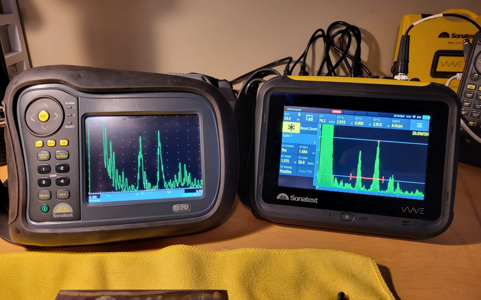
Thickness surveys of the floor plates are still necessary even though the entire floor should be 100% scanned. This helps cover a general radial pattern of the floor plates and also allows for inspection of sumps, pipeline connections and supports, landing pads, and repair patches. These areas can be difficult or impossible to inspect using other methods.
T-logging found on Sonatest systems, such as the Wave, Sitescan and Masterscan systems, helps record large data sets like floor spot reading grids.
For further information on our equipment and application notes, follow these links:
UT equipment, Thickness Gauges, Application notes
Corrosion Mapping
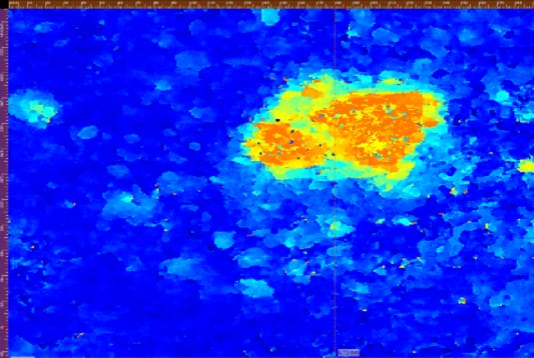
Ultrasonic corrosion mapping of tank floors usually focuses on specific areas where corrosion is detected by MFL scanning, or, in some cases, a 100% UT corrosion map scan can be performed on smaller diameter tanks. It is essential to accurately identify wall losses from the bottom side of the tank, as these are invisible from the external surface and can lead to pinhole failures that may release product into the environment unnoticed for a long period before detection.
Sonatest has multiple options for corrosion mapping from conventional UT and phased array to special scanners like the Wheel probe 2 (WP2). When combined with the VEO3, large areas can be scanned quickly, with high-fidelity data being recorded for review.
For further information on our equipment and application notes, follow these links:
Phased Array equipment, Scanners, WP2, Application notes
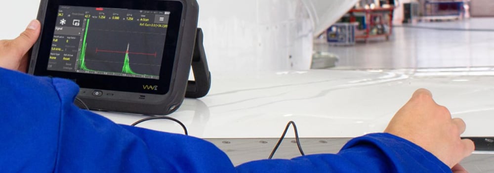
Weld Inspection
Various weld types can be found in tank floors, depending on the size and design. Annular plates are connected with butt welds, membrane plates with lap welding, and nozzle welds and T joints can also be found.
Typically, a set percentage of welds is inspected during manufacturing to ensure overall weld quality; however, some critical tanks may require 100% coverage of floor plate welds. Other reasons for inspection include repairs or routine checks.
Sonatest provides advanced equipment, transducers, and scanners to carry out weld inspections in all configurations and situations, with no cap on file size (up to the SSD size). This allows long welds to be inspected in a single pass, requiring only one file for the full weld review.
For further information on our equipment and application notes, follow these links:
Phased Array equipment, Scanners, Application notes
Please contact our Applications Team if you have any questions. You can also find more solutions on our website.
Stay up to date with our latest content. Sign up here to get our blogs delivered straight to your inbox.
News Filter...
The latest news from Sonatest direct to your inbox.
Tags