- Application Notes
PA-TFM for Long Seam Weld Inspection
Phased Array and TFM inspections of curved components can be challenging, especially for seam welds in small-diameter or heavy-wall pipes, as most inspection software tools and accessories are designed for flat surfaces. In these situations, configuration parameters require precise transmitted-ray modelling to reach defects within convex geometries.

Once the inspector defines the weld’s region of interest, the XEO applies its focus to the expected location. Its side view instantly resolves the propagated beams, ensuring full weld coverage. In addition, corrected scan views enable technicians to perform reliable flaw identification, interpretation, measurement, and sizing.
In addition, the measured depth of the flaw would change as the probe travels along the curved surface.
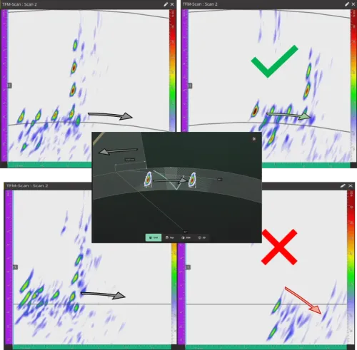
Fig. 1 - TFM on curved surface, flat versus pipeline geometry
Challenge with Phased Array on curved surfaces
Displaying a PAUT sectorial scan with an overlay representing the weld is very common. For flat surfaces, the skips in the sound path are addressed by representing the weld overlay as a series of folded images. However, for a curved surface, this method cannot be used because the reflected image formed by a convex surface is distorted, and a curved surface cannot be folded.
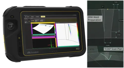
Fig. 2 - Example of a sectorial and a TFM on an Electric Resistance Welding (ERW)
Nowadays, the majority of long seam weld inspections focus on in-service mechanical damage detection—more specifically, for fatigue damage, such as a hook crack.
The image sharpness and resolution for such assessments are critical when it comes to flaw characterization. As a matter of fact, characterization mismatches may result in an increase of unnecessary repairs, such as an already accepted fabrication flaw.
Curved Scan Optimisation with An All-Focused Imaging: TFM & TFMiTM
Controlling the focusing distance on thin‑wall pipelines can be challenging, especially when the probe‑to‑weld centreline position varies or when the weld reference mark is difficult to follow. The Total Focusing Method provides an all‑focused pixel image that solves this issue. By laterally stretching the Region of Interest (ROI), probable weld defects remain detectable even when the probe position is not perfectly aligned.
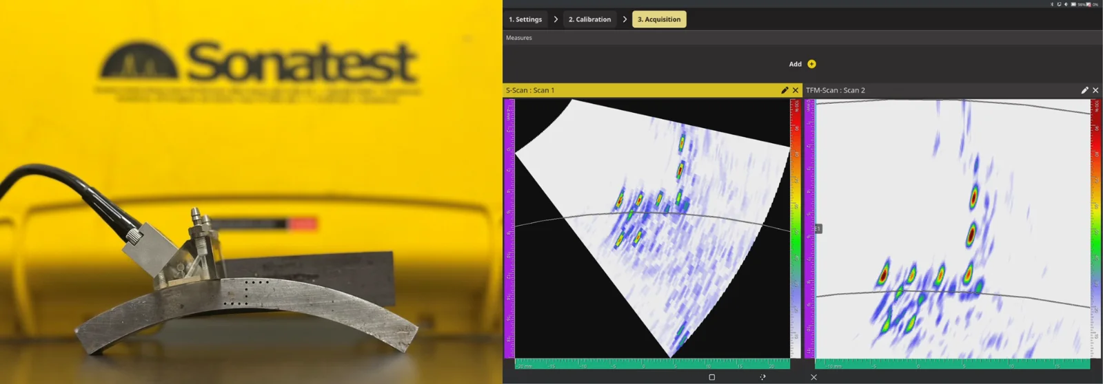
Fig. 3 - SDH line-up response from a sectorial and TFM scans
With the added benefits of TFM intermode characterisation , these techniques can also be applied to curved and curvature‑corrected components. The primary propagation modes remain standard TT-mode inspections, although additional trajectories, such as TTT or TTL, can be overlaid on the TT image when needed. Near‑vertical hook‑crack indications, commonly seen in ERW pipe welds, may also appear clearly in these TFMiTM scans.
By developing and integrating a wide range of scan‑planning tools, XEO delivers a smart and efficient workflow for evaluating seam welds.
Please contact our Applications Team if you have any questions. You can also find more solutions on our website.
Stay up to date with our latest content. Sign up here to get our blogs delivered straight to your inbox.
Filter by Industry
- Aerospace Aeronautical
- Aerospace Astronautical
- Chemical & Petrochemical
- Oil & Gas
- Nuclear Energy
- Wind Power Renewables
- Transport Network Infrastructure
- Rail
- Military
- Maritime Shipping
- Automotive
- Pharmaceutical
- Mining
- Construction & Infrastructure
- Technology & Research
- NDT Service Providers
- NDT Education


