Volumetric defects in welds include porosity, slag inclusion, internal cavities and metallic inclusions. These defects can significantly weaken the strength of the weld, and more seriously they can act as starting points for cracks that can expand over time.
Volumetric defects of a certain size can be acceptable but need monitoring to prevent crack propagation. Accurate sizing is crucial; poor initial sizing can lead to misreporting in future inspections, causing unnecessary shutdowns or even weld failure and loss of containment.
This blog explains the use of ultrasonic inspection techniques to detect two types of common volumetric defects within welds. It also highlights how Sonatest’s advanced equipment is currently being utilised in the field, showcasing our unique capabilities in improving the detection and sizing of these flaws.

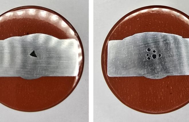
Fig. 1 – Slag inclusion (Left) and Grouped porosity (Right). Images of weld macros, supplied by Sonaspection.
Ultrasonic Methods
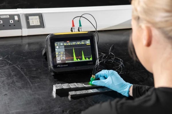
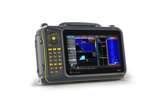
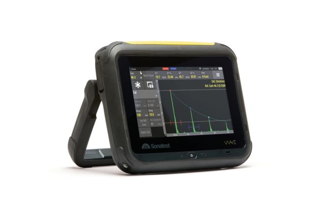
In this blog we have utilised the WAVE and VEO3 ultrasonic systems to scan and detect different examples of cracking, this shows the advantages of each method in the detection and sizing of each defect. The methods used are as follows:
- Conventional UT – Standard single element angled inspection; the most commonly accepted form of UT weld inspection used worldwide.
- Phased Array (PA) – PA inspection is an advanced ultrasonic technique that uses multiple element transducers to create ultrasonic beam sets at a given angle and focal point within the material.
- Time of Flight Diffraction (TOFD) – TOFD is a dual probe technique that detects and sizes flaws by measuring the time of flight for diffracted sound waves from the tips of flaws to travel through the material.
- Total Focusing Method (TFM) – TFM is an advanced ultrasonic imaging technique that uses FMC data to capture high-resolution images that are focused on every point of a region of interest.
- TFMi – TFMi is a unique technique developed in partnership with Holloway NDT that unites up to 4 TFM propagation modes into a single image, this produces high fidelity images of a defects’ shapes that other methods cannot define.
For more information on weld inspection using the above techniques see our library of application and solution notes.
Slag Inclusions
Slag inclusion refers to imperfections that result from the entrapment of slag within the weld material (Slag is a byproduct of the welding process). Inclusion of slag in the weld can occur due to several factors, the main being: Inadequate cleaning of the weld as well as incorrect welding settings and technique.
Slag inclusions generally have a rough surface and can vary greatly in size and orientation; this can scatter ultrasonic waves, leading to lower signal response and misinterpretation of the location of the defect. it is essential that these defects are inspected from both sides of the weld with full skip distances available. Inspector experience is crucial for the correct interpretation of defect positioning and identification.
As can be seen in the images below, this slag inclusion example was detected with all ultrasonic methods at a relatively low amplitude, with TFMi producing a high-quality & high-fidelity image of the crack (Figure 4—Right image), which was achieved using TTT and TTTT modes.

Fig. 2 – Slag inclusion weld profile (Left) Conventional UT detection on the Sonatest Wave (Right)

Fig. 3 – Slag inclusion detection as seen using TOFD (Left) and PA (Right) on the VEO3

Fig. 4 – Slag inclusion detection as seen in 4 x TFM modes (Left) and TFMi modes TTT and TTTT (Right)
Porosity
Porosity in welding is a common defect that occurs when gas pockets become trapped in the metal as it solidifies. It can be caused by many factors, including contamination of the weld with dirt or moisture, improper shielding of the weld, and poor welding technique. Some materials, like aluminium, are particularly vulnerable to porosity.
Pores can occur in groups or isolated; these weaken the weld structure, which can lead to cracking during the service of the weld. due to the rounded shape of pores, they can be difficult to find with ultrasound as the shape scatters the ultrasonic wave. use of ½ and full skip beam paths from both skews of the weld are essential to build up evidence for the inspector to Identify and classify porosity.
As can be seen in the images below, this grouped porosity example was detected with all ultrasonic methods at a relatively low amplitude, with TFMi producing a good image pulling those low-amplitude signals to show an image of the pores (Figure 7—Right image). This was achieved using TTT, TTTT, and 5T modes.

Fig. 5 – Porosity weld profile (Left) Conventional UT detection on the Sonatest Wave (Right)

Fig. 6 – Porosity detection as seen using TOFD (Left) and PA (Right) on the VEO3

Fig. 7 – Porosity detection as seen in 4 x TFM modes (Left) and TFMi modes TTT, TTTT and 5T (Right)
Please contact our Applications Team if you have any questions. You can also find more solutions on our website.
To follow further content and our newsletter, please contact us and check “Add to mailing list”.
News Filter...

The latest news from Sonatest direct to your inbox.
Tags


