Cracking in welds is a critical defect that can significantly compromise the integrity and safety of welded structures. These cracks can develop at any point during the lifespan of a weld.
Several factors, including improper welding techniques, thermal stress, cyclic loading, hydrogen embrittlement, and impacts may cause them.
This blog explores the use of ultrasonic inspection techniques to detect four types of common cracks in various positions within a weld. It also highlights how Sonatest’s advanced equipment is currently being utilized in the field, showcasing our unique capabilities in improving the detection and sizing of cracks.

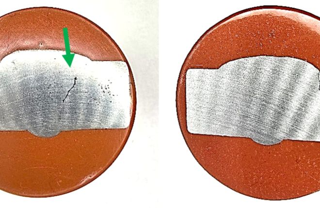
Fig. 1 – SW crack (Left) and Toe crack (Right). Images of weld macros, supplied by Sonaspection
Ultrasonic Methods
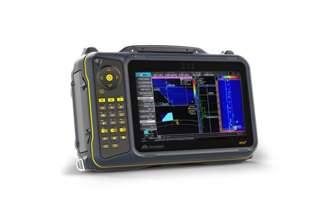
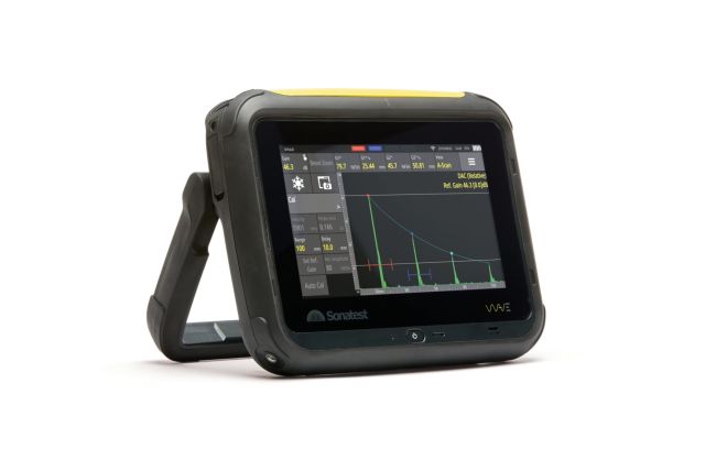
In this blog, we have utilised the WAVE and VEO3 ultrasonic systems to scan and detect different examples of cracking; this shows the advantages of each method in the detection and sizing of each defect. The methods used are as follows:
- Conventional UT – Standard single element angled inspection; the most accepted form of UT weld inspection used worldwide.
- Phased Array (PA) – PA inspection is an advanced ultrasonic technique that uses multiple element transducers to create ultrasonic beam sets at a given angle and focal point within the material.
- Time of Flight Diffraction (TOFD) – TOFD is a dual probe technique that detects and sizes flaws by measuring the time of flight for diffracted sound waves from the tips of flaws to travel through the material.
- Total Focusing Method (TFM) – TFM is an advanced ultrasonic imaging technique that uses FMC data to capture high-resolution images that are focused on every point of a region of interest.
- TFMi – TFMi is a unique technique developed in partnership with Holloway NDT that unites up to 4 TFM propagation modes into a single image. This produces high-fidelity images of defects’ shapes that other methods cannot define.
For more information on weld inspection using the above techniques see our library of application and solution notes.
Root Cracks
Root cracking is defined as a surface breaking crack emanating from the ID/ root area of a weld. This type of crack can be caused by cyclic loading of the weld during its service or at the point of welding by poor welding processes. Existing defects, such as incomplete penetration, root undercut, and incomplete fusion, can function as weak points, enabling cracks to start more easily.
Root cracks in general are one of the simpler defects for ultrasonic methods to detect, the back wall corner trap allowing for high amplitude responses, and tip diffractions to aid in determining the height of the crack.
As can be seen in the images below, this root crack example was detected easily with all ultrasonic methods. TFMi produced a very high-quality and high-fidelity image of the crack (Figure 4 – Right image), which was achieved using TT, TTT, and TTTT modes.

Fig. 2 – Root crack weld profile (Left) Conventional UT detection on the Sonatest Wave (Right)

Fig. 3 – Root crack detection as seen using TOFD (Left) and PA (Right) on the VEO3

Fig. 4 – Root crack detection as seen in 4 x TFM modes (Left) and TFMi modes TT, TTT and TTTT (Right)
Side Wall Cracks
Side wall cracking usually occurs along the prep face of the weld or in the heat-affected zone (HAZ) of the weld. Wholly contained within the material, this type of crack often results from poor welding practices or originates from other internal defects during service.
Due to the orientation of side wall cracks, the ultrasonic signal can appear in the wrong place in the weld. Therefore, these defects must be inspected from both sides of the weld with full skip distances available. Inspector experience is crucial for the correct interpretation of defect positioning and identification.
The scan images below show good detection of the crack. The PA and TFM in TTTT mode show exceptionally good imaging of the defect, with TFM in TT mode displaying tip diffraction signals from the top and bottom of the defect for accurate sizing. The TFM imaging (TFMi) shows the shape of the crack in great detail, even detailing the breakaway of the crack into the HAZ area. This image used TTTT and 5T to achieve this level of detail.

Fig. 5 – Side wall crack weld profile (Left) Conventional UT detection on the Sonatest Wave (Right)
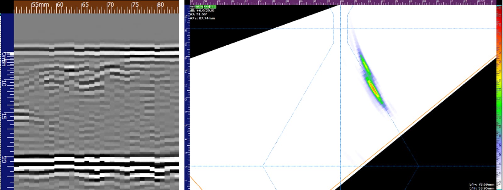
Fig. 6 – Side wall crack detection as seen using TOFD (Left) and PA (Right) on the VEO3

Fig. 7 – Side wall crack detection as seen in 4 x TFM modes (Left) and TFMi modes TTTT and 5T (Right)
Toe Cracks
Toe cracks appear adjacent to or along the line of the toe of a weld cap. Breaking the surface of the material, these defects can usually be detected using surface inspection methods. However, there are circumstances in which this defect can be missed: tight/small cracking can be hard to see, cold lapping may hide the opening of a crack, etc. Post-weld and in-service inspections with UT methods are vital to the detection of these defects early.
Toe cracks require the use of full skip inspections to allow the signal to reach the defect area, high angle ½ skip may detect severe cracking but can be unreliable in sizing the depth of the crack.
As seen below, all methods detected the toe crack with reliable results, the TFM TT and TTT modes were found to be weaker in detection compared to the TTTT and 5T methods, however, weaker signals were detected. The TFMi shows the crack in great detail using TT, TTT, TTTT and 5T modes to create this image.

Fig. 8 – Toe crack weld profile (Left) Conventional UT detection on the Sonatest Wave (Right)

Fig. 9 – Toe crack detection as seen using TOFD (Left) and PA (Right) on the VEO3

Fig. 10 - Toe crack detection as seen in 4 x TFM modes (Left) and TFMi modes TT, TTT, TTTT and 5T (Right)
Centre Line Cracks
Centre line cracking occurs in the middle of the weld, or in larger multi run welds the same process can occur between weld passes. This type of carack can be surface breaking or embedded within the weld and is caused by thermal stresses, poor weld prep or poor welding procedures.
Centre-line cracking can be difficult to interpret as reflections from the defect can be ‘cast’ off, making the plotted indication appear in various locations of the weld. Inspections from both sides of the weld with ½ and full skips available are vital to gather evidence to aid in the correct interpretation and positioning of this crack.
In the scans below, all methods detected the centre line crack; the PA and TFM scans show some positioning inaccuracies caused by the signal reflecting in other directions than straight back to the probe. The TOFD and TFMi have particularly good responses, the TOFD taking advantage of its high sensitivity to defects in any orientation. The TFMi shows the crack in great detail in the correct position using only TT and TTT modes.

Fig. 11 – Centre line crack weld profile (Left) Conventional UT detection on the Sonatest Wave (Right)

Fig. 12 – Centre line crack detection as seen using TOFD (Left) and PA (Right) on the VEO3

Fig. 13 – Centre line crack detection as seen in 4 x TFM modes (Left) and TFMi modes TT and TTT (Right)
Please contact our Applications Team if you have any questions. You can also find more solutions on our website.
Stay up to date with our latest content. Sign up here to get our blogs delivered straight to your inbox.
News Filter...
The latest news from Sonatest direct to your inbox.
Tags

