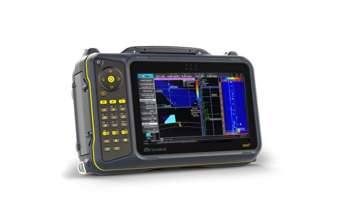
Nozzle Inspection
Nozzle welds can provide unique challenges for inspection, Complex geometries including changing surface curvatures, nozzles offset from center, material thickness transitions and access limitations mean that inspection of nozzle welds is a complex and highly skilled operation.
See also our educational note detailing the inspection of welds in nozzles nodes and curved surfaces (pdf, 925kb).
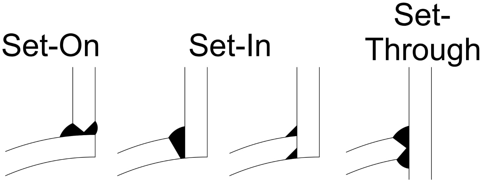
Figure 1 – Examples of the variation in nozzle welds
Inspection Methods
Multiple inspection methods are available to assess pipeline welds; these include surface methods such as Visual, Magnetic Particle, Dye Penetrant and Eddy Current inspection; these only inform the inspector of the condition of the surface and slight subsurface of the weld. Full volumetric inspection requires Ultrasonic methods (UT) or Radiography (RAD).
UT has many advantages over RAD, the main ones being:
- UT produces no radiation hazard and can be conducted alongside other personnel; this is a safer process than radiography and means the site does not need to be cleared of workers for the inspection to take place
- UT is sensitive to small defects, cracking defects and planar lack of fusion defects making it an excellent application for thinner pipework but is also applicable for thicker materials
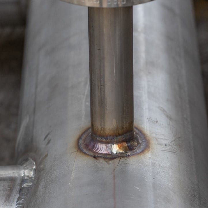
Figure 2 – Example of a nozzle weld
Inspection Challenges
Nozzles present one of the most challenging inspections for an NDT inspector, The nozzle type, angle of insertion, weld type, material, and thickness changes all need to be considered in defect detection and evaluation. Alongside these are significant access challenges, often causing areas of restricted access or even single-sided access only.
When choosing an ultrasonic inspection method for nozzles all the above details need to be known to plan and execute the inspection
Types of Ultrasonic Inspection Used
Conventional Ultrasonic Inspection (UT)
UT utilizes single or dual crystal transducers in single-beam configurations to interrogate a weld. Transducers are set to produce specific known angles in the material (usually 0°, 45°, 60° and 70°, but other angles can be used). Manual ‘scanning’ or movement of the transducer on the surface ensures coverage of the weld. Return signals are interpreted by the inspector to detect and size defects.
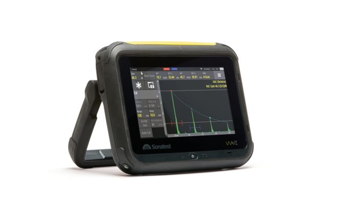
See our Wave Nozzle Inspection application note (pdf, 925kb) for further details.
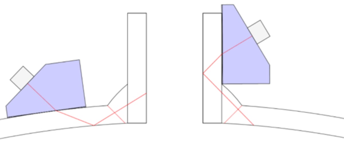
Figure 3 – Example scan positions for a conventional UT inspection of a nozzle
Phased Array (PA)
A PA inspection is carried out using a transducer containing multiple individual elements in an array. These elements are pulsed individually or in groups to create a beam that can be directed and focused depending on the inspector requirements. PA inspection can inspect full weld volumes in a single sweep or interrogate specific areas of a weld and produces a recorded data file with views that can be manipulated to aid interpretation.
See our solution note for the inspection of nozzles with PA (pdf, 700kb) here.
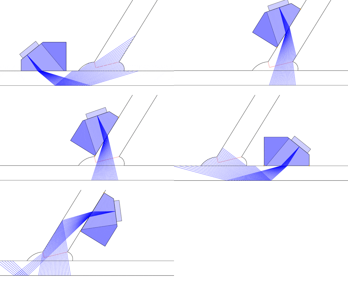
Figure 4 - Examples of probe positions for required for full coverage
Scanners
Inspections of nozzles are often performed manually, with a technician positioning the probe at the proper offset from the weld and using an encoder wheel to pull the scan. This method relies on the technicians ‘steady hands to maintain the proper offset for accurate results, and is unavoidable in some nozzle geometries.
Where possible, nozzle scanners can be utilized to set the transducer in the correct position and carry out an accurately encoded 360° scan in a single pass.

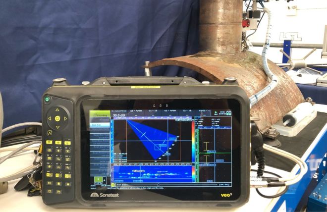
Figure 5 - VEO3 phased array scan utilizing the Phoenix ISL NozzleScan
Please contact our Applications Team if you have any questions. You can also find more solutions on our website.
To follow further content and our newsletter, please contact us and check “Add to mailing list”.
News Filter...
The latest news from Sonatest direct to your inbox.
Tags

