- Application Notes
Ultrasonic Rail Solid Axle Inspection with the Sonatest Wave
Rail axles predominately come in 2 different styles, hollow and solid, the dimensions of which can vary depending on the type of rail which the trains run on. For this application note we will be looking at the inspection of a VLU type rail axle used on underground trains in London.
There are 3 different axle types in this class, all with different areas for geometrical reflections, please see images below:

Fig. 1 - Standard solid Axle with two wheel seats

Fig. 2 - Solid Axle with features for a drive unit

Fig. 3 - Solid axle with additional features for drive unit and gear box
The axle shown in Figure 1 is the axle type inspected for this trial. This axle only has wheel location points, the additional grooves in the remaining two types of axle are for gear boxes and drive wheels, these are more complicated inspections as there are many more geometric indications to be seen during the scanning.
These trials were carried out on a training axle (pictured in Fig. 4). This has the same 3two wheel seat features as in Fig. 1 at the near/far end (depending on which side you are standing) then also 1 in the centre of the axle. The 2 near/far end are approx. 1.5mm deep saw cuts, the centre is an approx. 3mm saw cut. The two images to the right of the full axle are the visible defects (one defect is hidden below the wheelset).

Fig. 4 - Training Axle used for the inspection trial
Inspection Procedure
Far end scan:
- The far end scan consists of using either a 0-degree or 5-degree transducer, this scan covers the body mid span of the axle.
- The A-Scan images below show an example of a good and defective sample, the defect in the defected sample is circled and shows at around 1000 mm, this is the centre of the axle.

Fig. 5 - Far end scan results, Left image shows a ‘good’ axle, Right image shows a defect located in the axle
Near end scan:
- The near end scan consists of using a 12.5-degree or 20-degree angle to inspect the inner wheelset and the wheelset transition area.
- The A-Scan images below show an example of a good and defective near end scan using a 20 degree angle. The first image is good, the second image shows 2 defects, one in the inner wheelset (first circle) the second in the wheelset transition (second circle).

Fig. 6 - Near end scan results, Left image shows a ‘good’ axle, Right image shows a defect located in the axle
Scan Plan
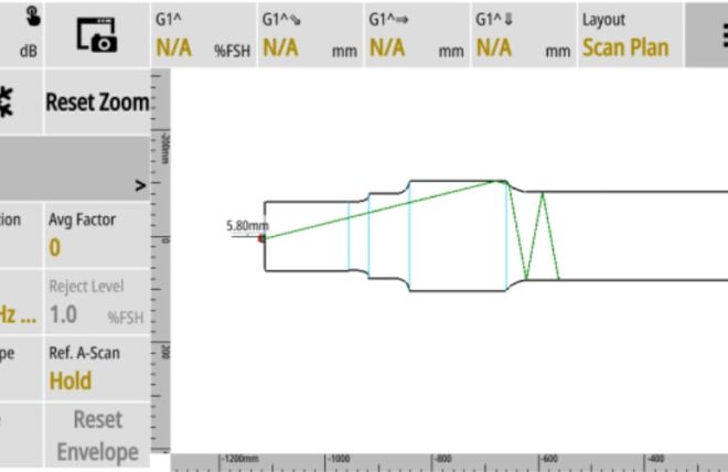
The WAVE can show the centre beam location within the axle on the scan plan feature, this allows for the import of DXF CAD files to be used as an interactive scan plan as seen in Fig. 7.

Fig. 7 - Image of the WAVE scan plan with an imported DXF axle file and the transducer beam within the part
Conclusion
Axle inspection is a difficult but efficient method to detect cracking and inclusions throughout various axle style. The Sonatest Wave flaw detector gives superior signal to noise as well as a simple platform to make the process as smooth as possible.
Recommended Tool Package
| Category | Part# | Description |
|---|---|---|
| Acquisition Unit | WAVE digital flaw detector | |
| Probe | Rail axle transducers (angle and frequency specific for the type of axle being inspected) | |
| Software | WAVE Companion Software |
Please contact our Applications Team if you have any questions. You can also find more solutions on our website.
Stay up to date with our latest content. Sign up here to get our blogs delivered straight to your inbox.
Filter by Industry
- Aerospace Aeronautical
- Aerospace Astronautical
- Chemical & Petrochemical
- Oil & Gas
- Nuclear Energy
- Wind Power Renewables
- Transport Network Infrastructure
- Rail
- Military
- Maritime Shipping
- Automotive
- Pharmaceutical
- Mining
- Construction & Infrastructure
- Technology & Research
- NDT Service Providers
- NDT Education
Related Products
