- Application Notes
TFMi™ Inspection for monitoring "Blind" Holes
It is sometimes necessary to drill holes with very large depth-to-diameter ratios. A common approach is gun drilling, whereby a cutter is used at the end of a long rotating tool. Ensuring the alignment and consistent diameter of long holes represents an inspection challenge. The Veo3 TFMi™ feature developed in partnership with Holloway NDT provides a useful option when the hole is parallel to nearby surfaces.

Using the TFMi™
NDT technique in the veo3, with the Intermodal set to “Keep Max.” shows the reflected signal from the top surface (LL mode) and the bottom surface (LLLL mode) correctly positioned on screen. A simple gate can be used to measure the gap between them.
With the instrument set to a single propagation mode TFM scan only one of the surfaces can be imaged at one time.
Setting the instrument to TFMi™ mode allows us to use up to 4 propagation modes at once. Using the “Keep Max” viewing mode we can see the un-altered results from each mode overlayed on top of each other.
In this inspection we utilised LL and LLLL modes to show the top and bottom reflections from the blind holes. This requires the thickness of the part to be known. For the block used in this study we used a thickness of 50mm (see Fig. 1).

Fig. 1 - Test block and side drilled holes used in the study, the holes can be seen to decrease in size from left to right

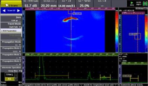
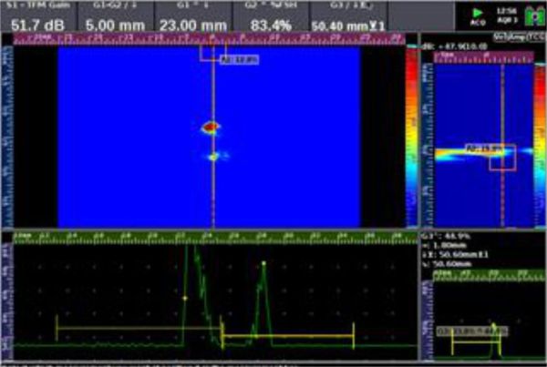
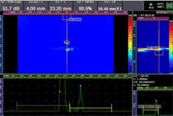
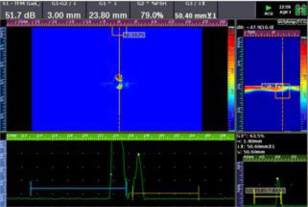
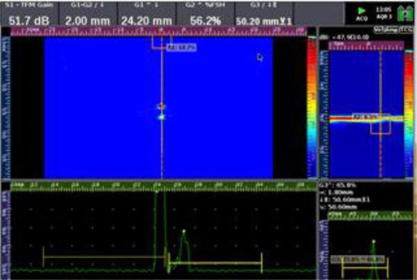
Fig. 2 - Example TFMi™ scan set to LL/LLLL keep max mode showing the upper reflections detected by the LL scan and the bottom reflections detected by the LLLL scan, the second image shows the beam paths taken by each mode to produce the image
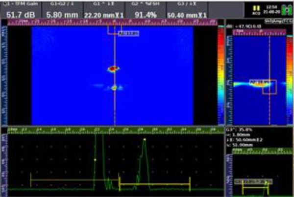
NOTE when inspecting the larger holes the bottom signal is weaker, this is because the hole is nearly 75% of the size of the probe aperture, this blocks some of the signal to and from the back wall. With the correct gate positioning, avoiding the diffraction signals we can still get an accurate measurement of hole size.

Fig. 3 - Showing a weak signal from the bottom of the largest hole
Results
| Hole 1 Diameter measurements | |||
|---|---|---|---|
| Digital Calliper Results | 20.03mm | TFMi™ Results | 20.20mm |
| Hole 2 Diameter measurements | |||
|---|---|---|---|
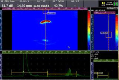
| Digital Calliper Results | 15.05mm | TFMi™ Results | 14.60mm |
| Hole 3 Diameter measurements | |||
|---|---|---|---|
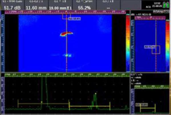
| Digital Calliper Results | 11.97mm | TFMi™ Results | 11.60mm |

| Hole 4 Diameter measurements | |||
|---|---|---|---|
| Digital Calliper Results | 10.02mm | TFMi™ Results | 10.00mm |

| Hole 5 Diameter measurements | |||
|---|---|---|---|
| Digital Calliper Results | 8.03mm | TFMi™ Results | 7.80mm |
| Hole 6 Diameter measurements | |||
|---|---|---|---|
| Digital Calliper Results | 6.11mm | TFMi™ Results | 5.80mm |
| Hole 7 Diameter measurements | |||
|---|---|---|---|
| Digital Calliper Results | 5.08mm | TFMi™ Results | 5.00mm |
| Hole 8 Diameter measurements | |||
|---|---|---|---|
| Digital Calliper Results | 4.07mm | TFMi™ Results | 4.00mm |
| Hole 9 Diameter measurements | |||
|---|---|---|---|
| Digital Calliper Results | 2.93mm | TFMi™ Results | 3.00mm |
| Hole 10 Diameter measurements | |||
|---|---|---|---|
| Digital Calliper Results | 1.60mm | TFMi™ Results | 2.00mm |
Conclusion
Blind hole inspection is an excellent fit for TFMi™. It really enables a full comprehensive profile view of the internal geometry of a part. The benefit of displaying many propagation modes at the same time has improved complex geometry assessment just as it has been demonstrated in this app note.
There are other similar potential geometry challenges like this where keep max TFMiTM imaging could improve on current inspection methods. Indeed, other propagation modes e.g. LLL or any other shear modes could be utilised with TFMi™ keep-max processing, so additional planar or volumetric features could be added in TFMi™ view.
Recommended Tool Package
| Category | Part # |
|---|---|
| Acquisition Unit | VEO3 UT BNC KIT or VEO3 UT LEMO KIT |
| Probe | X3A-003 or D5A-001 |
Please contact our Applications Team if you have any questions. You can also find more solutions on our website.
Stay up to date with our latest content. Sign up here to get our blogs delivered straight to your inbox.
Filter by Industry
- Aerospace Aeronautical
- Aerospace Astronautical
- Chemical & Petrochemical
- Oil & Gas
- Nuclear Energy
- Wind Power Renewables
- Transport Network Infrastructure
- Rail
- Military
- Maritime Shipping
- Automotive
- Pharmaceutical
- Mining
- Construction & Infrastructure
- Technology & Research
- NDT Service Providers
- NDT Education
Related Products
