- Application Notes
Rail Bolt Hole Inspection
Inspection of bolt holes in rail is a common task required by rail standards that detects cracking caused by expansion and vibration. Crack in bolt holes gradually expand and can cause a whole section of the rail to become separated from the whole, this has the potential to cause derailment and in turn loss of life. Because of this risk, bolt holes are monitored regularly for developing defects.
Historically the most commonly used method for this inspection is conventional ultrasound with shear wave angled transducers, the inspector must use a variety of angled transducers to cover the bolt hole fully, and a different offset position for each hole.
This application note highlights the use of phased array ultrasonics to reliably perform the bolt hole inspection in a repeatable and more time efficient manner. Phased array also offers additional ways to view the data allowing for quicker defect identification and more accurate sizing.
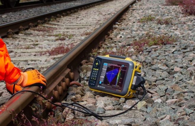
Fig. 1 - Phased array inspection of bolt holes (PRISMA)
Figure 2 shows a typical scan plan, detailing how the inspector uses ½ and full skip methods from both side of the bolt hole to achieve full coverage of the hole circumference.
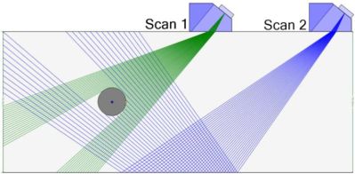
Fig. 2 - Scan plan example of ½ skip (Scan 1) and full skip (Scan 2) methods for coverage of the bolt hole
The four images below show the bolt hole with and without defects:

Fig. 3 - ½ skip inspection. Bolt hole with no defects (left) and a bolt hole with cracking on both sides (right)
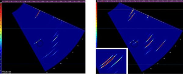
Fig. 4 - Full skip inspection. Bolt hole with no defects (left) and a bolt hole with multiple cracks (right)
The left image in Figure 3 shows the response going direct onto the bolt hole, this produces one reflection from the hole. The right image in Figure 3 shows the same direct scan, this time hitting 3 or 4 defects around the hole. It is possible to differentiate the top response as a defect rather than geometry because it's two separate reflections close together.
Figure 4 shows the scan images of the bottom side of the bolt hole, this time skipping is needed as shown in Figure 2, when the sound is reflected up from the bottom of the track in order to get full coverage. The left image in Figure 4 shows the response with no defect, whereas the right image in Figure 4 shows the hole with two defects. The zoomed in image shows the two reflections from the right hand signal.
Recommended Tool Package
| Category | Part# | Description |
|---|---|---|
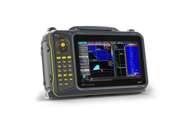
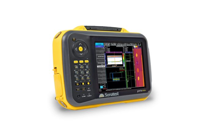
| Acquisition Unit | VEO3 / PRISMA data acquisition units | |
| Probe | X5A Range of deep penetration PA transducers and accompanied wedges | |
| Encoder | AXYS Encoder |
Please contact our Applications Team if you have any questions. You can also find more solutions on our website.
To follow further content and our newsletter, please contact us and check “Add to mailing list”.
Filter by Industry
- Aerospace Aeronautical
- Aerospace Astronautical
- Chemical & Petrochemical
- Oil & Gas
- Nuclear Energy
- Wind Power Renewables
- Transport Network Infrastructure
- Rail
- Military
- Maritime Shipping
- Automotive
- Pharmaceutical
- Mining
- Construction & Infrastructure
- Technology & Research
- NDT Service Providers
- NDT Education
