

Phased Array Ultrasonic Testing (PAUT) first entered the AWS structural welding codes with AWS D1.5:2015, which introduced PAUT requirements for bridge weld inspection. AWS D1.1 followed in 2020.
In 2025, the PAUT provisions were brought into alignment, with AWS D1.5 revising its Advanced Ultrasonic Examination Annex J to align with AWS D1.1 Annex H.
The result is a well-defined PAUT workflow covering scan planning, equipment and probe verification, calibration, encoded data collection, evaluation, and reporting.
For D1.1, Annex H applies to PAUT examination of groove welds and their heat-affected zones from 3/16 in. to 8 in. [5 mm to 200 mm] using encoded linear scanning.
Personnel collecting or analyzing PAUT data also have additional qualification requirements, including 320 hours of documented PAUT work experience and a practical examination using flawed specimens representative of the joints being examined.
Plan the Inspection
A compliant PAUT inspection starts before the probe ever touches the weld.
The scan plan establishes the weld geometry, probe and wedge, focal laws, probe positions, and other variables needed to demonstrate coverage of the required examination volume. AWS requires that coverage be demonstrated by plotting or computer simulation.
Azimuthal, or sectorial scans are used as the primary technique, with angular increments no greater than 1 degree. Electronic scans may supplement the sectorial scans but aren't used as the sole inspection technique. The plan also needs to account for coverage from the required directions and orientation to the weld fusion faces.
This is a good application for the Sonatest XEO's onboard 3D ray tracing. The probe, wedge, weld geometry, and sound paths can be viewed together while the setup is being developed, making it easier to see where the beams are actually going rather than relying only on a conventional 2D scan-plan drawing.
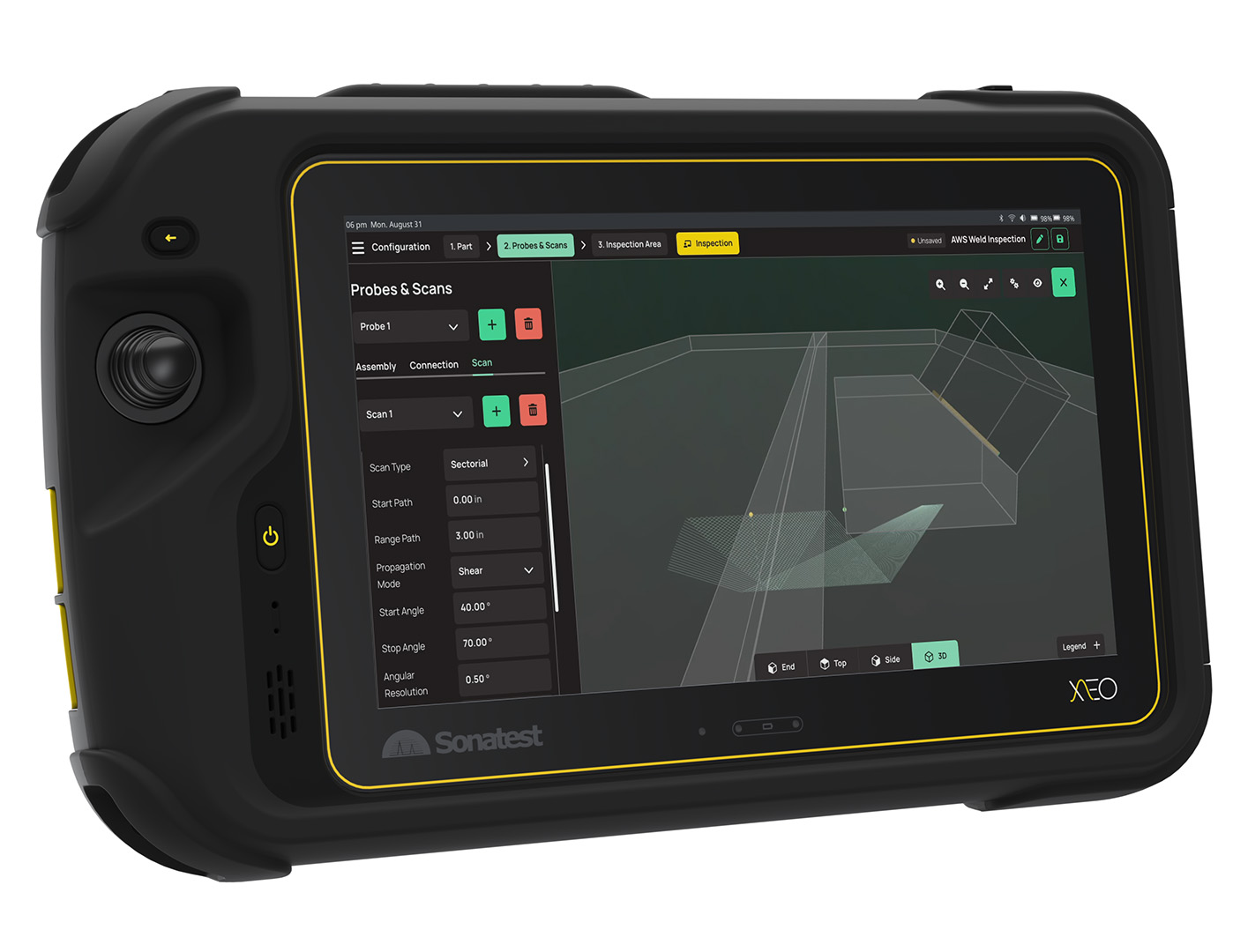
Figure 1 - Visualizing weld coverage during scan-plan development.
For setups requiring two PA probes, the XEO can also be fitted with a dual 64-channel MiniDock, allowing both probes to connect directly to the instrument without an external probe splitter.
Verify and Calibrate the System
Before calibration, AWS requires an element operability check of the phased array probe.
No more than 10% of the elements within an aperture may be dead, no more than two adjacent elements may be dead, and individual element responses must remain within 6 dB of the average response across the aperture. The check is required before initial calibration and use, weekly, and during each eight-hour period of use. The XEO element checker makes this a straightforward process. The applicable limits can be entered into the check and the probe automatically evaluated against the acceptance criteria.
The Calibration Dashboard then provides a central view of the element check and the other required calibrations across the configured probes and scans.
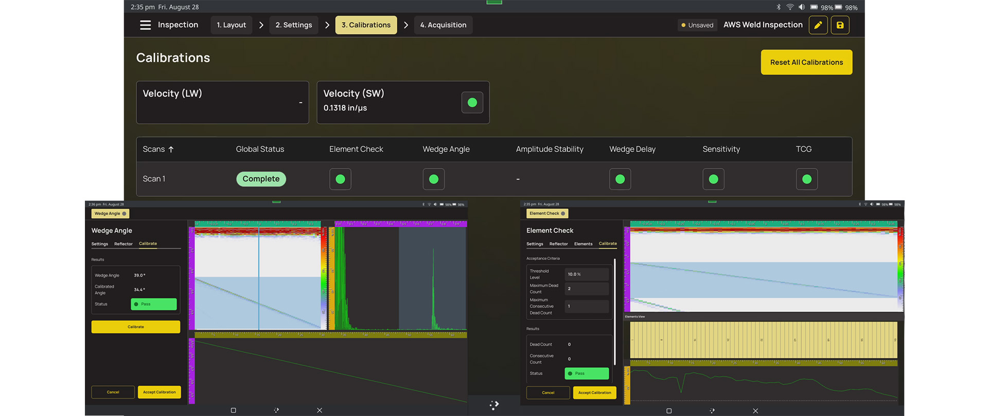
Figure 2 – Calibration Dashboard with Element Check, and Wedge Angle Calibration wizards.
For angle-beam inspection, the calibration process includes:
- Beam-Angle Verification
- Horizontal Sweep/Wedge-Delay Calibration
- TCG
- Sensitivity
- Encoder Calibration
TCG is established through all configured angles using at least three reference points through the examination range. Those points are balanced within +/-5% amplitude.
Sensitivity is then established using the 0.060 in. [1.5 mm] side-drilled hole on an IIW block. The Standard Sensitivity Level (SSL) is set to 50% +/-5% FSH. For dynamic line scanning, 4 dB is added to account for acquisition losses. That sensitivity becomes important later during evaluation.
Collect the Data
AWS PAUT is primarily an encoded line-scan inspection. Each A-scan is recorded along with its position on the weld, creating a data file that can be evaluated after the scan is complete.
Encoder resolution is set so that data is collected at increments of 0.04 in. [1 mm] or smaller, and the encoder is verified through daily in-process checks.
AWS also requires the original A-scan data to be recorded without exclusionary gating or filtering other than receiver bandpass filtering. Data dropout cannot exceed 1%, and two consecutive scan lines cannot be missed.
The acquisition screen itself doesn't need to be crowded. For example, an inspector may choose to scan with only a large S-scan and C-scan visible.
On the XEO, inspection layouts are customizable, with views that can be dragged, resized, and arranged around the job.
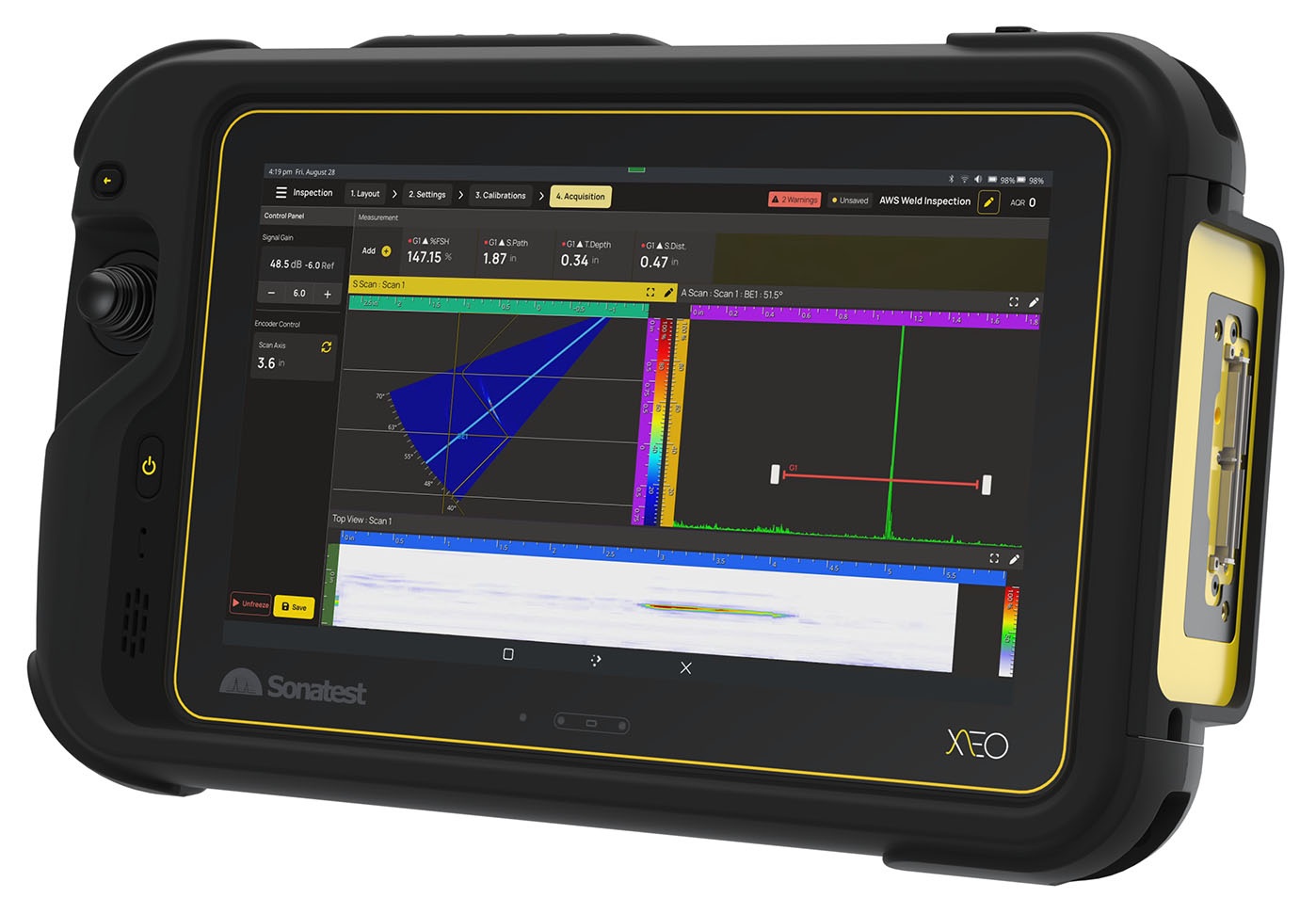
Figure 3 - A simple acquisition layout for encoded weld scanning.
Evaluate the Indications
AWS PAUT uses three reference levels to classify indications:
- ARL - Automatic Reject Level: 5 dB above SSL
- SSL - Standard Sensitivity Level
- DRL - Disregard Level: 6 dB below SSL
These levels divide indications into four amplitude classes:
- Class A - Above ARL
- Class B - Between SSL and ARL
- Class C - Between DRL and SSL
- Class D - Below DRL
Amplitude alone doesn't determine acceptance. Indication length and loading condition also matter. For a statically loaded structure, the acceptance criteria is:
- Class A - None allowed
- Class B – up to 3/4 in. [20 mm] allowed
- Class C – up to 2 in. [50 mm] allowed
- Class D - Disregard
AWS also states that welds are acceptable only when they contain no planar indications and no indications exceeding the applicable amplitude or length limits. Indications characterized as cracks are unacceptable regardless of amplitude or length.
Indication length is determined using the 6 dB drop method. This can be measured using cursors during the analysis phase. There are also proximity rules for Class B and C indications: indications that are too close together may need to be treated as a single indication.
Encoded data makes this evaluation much easier to visualize. During acquisition, an inspector may only need the S-scan and C-scan. During analysis, the same XEO file can be arranged differently, adding the A-scan and B-scan for a closer look at the signal, depth, and length of an indication.
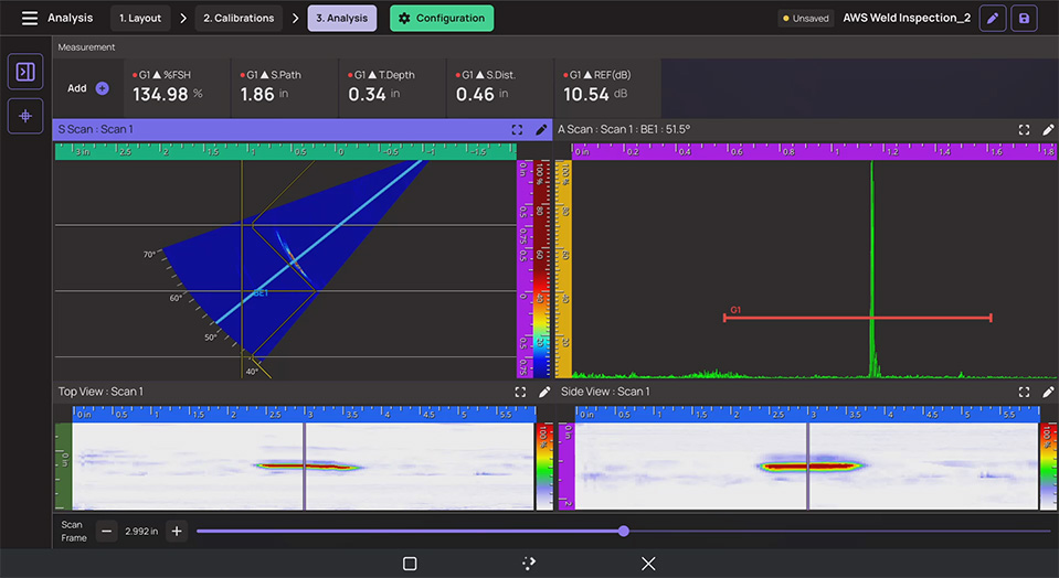
Figure 4 - Reconfiguring the inspection data for indication evaluation. Note that this indication is measured at 10.38 dB above reference level, well above the ARL (Auto-Reject Level) making this indication easily reject worthy.
Document the Inspection
The final step is maintaining a record that supports the inspection results.
AWS requires the original raw A-scan data to be retained, and subsequent analysis can't alter that original data. The scan plan also accompanies the examination report.
When PAUT is substituted for radiography, the reporting requirements include an encoded C-scan covering the complete inspected length and A-, B-, C-, and S-scan views of reportable indications.
That is one of the major advantages of encoded PAUT: the inspection isn't limited to the technician's interpretation while standing at the weld. The scan, calibration status, and indication data remain available for later review.
Modern instruments like the XEO continue to make that workflow easier. With features such as 3D scan planning, guided calibration and element checking, customizable acquisition and analysis layouts, and interchangeable Mini Docks, the XEO keeps the focus on the inspection while AWS defines what that inspection needs to accomplish.
Get in touch with your local Sonatest expert, available in more than 50 countries over 5 continents!
News Filter...
The latest news from Sonatest direct to your inbox.
Tags
- Phased Array
- Careers
- Exhibitions
- TFM
- CRFRP
- Composite Materials
- UT Testing
- WheelProbe 2
- Wave
- Software Update
- Transducers
- Education
- Weld Inspection
- Corrosion Mapping
- Ultrasonic Testing
- alphagage+
- Linear Scan
- Pipeline Integrity
- User Story
- Weldments Advanced UT
- metals
- Austentic steels
- Pipelines
- Storage Vessel
- Pressure Vessel
- Rail
- Boiler
- Flanges
- Nozzels


