

In the ultrasonic NDT business, inspection companies regularly encounter situations in which they need to inspect complex geometries. The main challenge is to accurately determine the beam path to locate indications in a part correctly.
Incorrectly plotting an indication can lead to incorrect positioning, false calls, missed defects, leading to unnecessary repairs, financial loss and, more importantly, safety issues.
To solve this problem in conventional ultrasonic, the industry has historically used hand-drawn scan plans and beam profiles, whereby experts define the part they inspect and ensure coverage in the area of interest. All of this was performed on paper or more recently on a software like BeamTool. Technicians would then use these diagrams alongside their UT inspection units.
It is clear there is an advantage to having this scan plan embedded in the instrument. This feature enables users to make quick validations and reduce human errors associated with transferring digital data to a physical measurement.

Live Scan Plan Interactivity based on a BeamTool Sketch
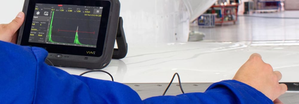
Mono-beam inspections require a high skill level and fast interpretation during raster and skewing moves. The Wave Interactive Scan Plan renders the part geometry and full A-Scan, showing multiple skips and accurate refracted angles within the part, where the plotting of the ray tracing is very difficult to judge by the inspector’s “eye” alone. The precision of the ray tracer shown visually is much better than human hunch when a defect is identified during the first instance. Avoiding critical false calls is the main premise of the Wave Scan Plan feature.

The backwall has been precisely located by the ray tracer
When dealing with complex geometries, systems are often limited to a set of pre-defined standard profiles. To enable inspections of all shapes and dimensions, an imported CAD diagram allows users to create profiles of highly complex geometries and still accurately show beam tracings within parts.
Here is an example of a complex geometry part. There is a cross-section of a reducer nozzle that requires an inspection. With an imported CAD diagram, you can see accessibility issues and the beam coverage that can be achieved with this part. As industries continually develop solutions and new designs, the need for accurately inspecting these types of parts becomes more important than ever before.

Example of a complex geometry part
Three years ago, Sonatest launched the first advanced conventional ultrasonic flaw detector with an embedded scan plan. This feature enabled Wave owners and users to be more confident with their findings when performing ultrasonic assessments. Once again, Sonatest has improved the Wave by adding CAD file imports into its new 1.8 software release. This is a game changer, and until now, it was an option only available in PC-based programs and phased array instruments.
Please contact our Applications Team if you have any questions. You can also find more solutions on our website.
Stay up to date with our latest content. Sign up here to get our blogs delivered straight to your inbox.
News Filter...
The latest news from Sonatest direct to your inbox.
Tags
Related Products
