
Assembling and building pipelines in the oil and gas industry necessitates a rigorous quality assurance process to ensure the asset can withstand pressure and perform reliably over time.
In this post, we will explore a widely used ultrasonic inspection method that employs single crystal probes. We will highlight key points and best practices for both pipe butt welds (AOD wedges) and axial welds (COD wedges).
AOD Inspections

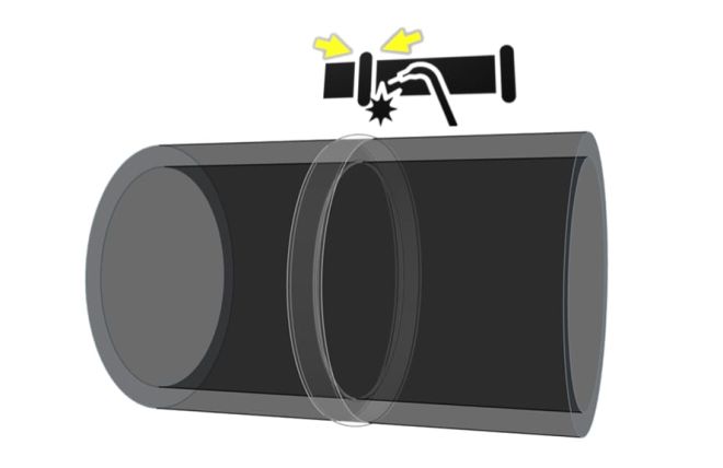
Fig. 1 - AOD Inspection for Butt Welds
All pipelines must be joined together, as displayed above, and the common and most straightforward assembly technique requires joining the two ends together. Basic ultrasound testing and interactive scan plans provide a comprehensive NDT method for quality assurance. Please have a look at the application to understand the Wave advantages around butt welds of different kinds.
Ultrasonic Butt Weld Inspection
COD Inspections
The rationale behind COD inspection for seam (axial) welds differs from that for butt welds. Single-angle evaluations introduce uncertainties due to complex reflections from the back wall and weld geometry. There are five key factors to control when performing a COD weld inspection: joint type, the maximum and minimum effective angles based on part thickness, the optimum angle of reflection, the expected damage associated with service and the fusion process, and the probe specification. Otherwise, there is a risk of misinterpreting the A-scan and measurement results.

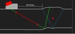
Fig. 2 - COD Inspection for Axial Welds
| Key Points to Control Before the Evaluation | Help and Guidelines |
|---|---|
|
Nominal thickness change by the weld location |
Check the drawings if available or use a 0-degree probe to gather the true thickness. |
|
The weld overlay dimensions, shape, root location, etc.
|
Get the most information as you can and build the weld overlay live on screen or import and apply the DXF if it is too complex. It is recommended on ERW welds to use zero-degree checks to plot joint shape and extremities. |
|
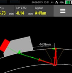
Defect locations with curve compensation, probe location with many skips
|
Skips versus probe offset position versus the weld location is critical, but once the interactive scan plan details are validated, the measurements are trustworthy. Extra note: The Wave true depth measurements accounts for skips and surface distance thickness. The true depth is positive downwards and negative when it the location is above the surface. E.g.: The echo by the top weld crown is above the OD interface. See the screenshot on the left. |
The Wave guides inspectors weld after weld, regardless of part complexity. For accurate, reliable reports and confident evaluations, ensure you fully understand and utilize the interactive scan plan. Pipeline welds should no longer be a source of uncertainty.
Please contact our Applications Team if you have any questions. You can also find more solutions on our website.
Stay up to date with our latest content. Sign up here to get our blogs delivered straight to your inbox.
News Filter...
The latest news from Sonatest direct to your inbox.
Tags
Related Products
