
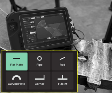
XEO now features a practical and intuitive 3D Part Builder designed to simplify weld inspections. In this blog, we explore the key capabilities of the XEO setup builder and how they help create accurate, efficient, and repeatable inspection configurations.

A successful inspection begins with an accurate representation of the component. As soon as the Configuration environment opens, the Part Builder displays the main parameters required to define the inspection geometry. The Part menu allows users to select from six common geometries, including plates, pipes, rods, curved components, corners, and T-joints, before entering the corresponding dimensions.
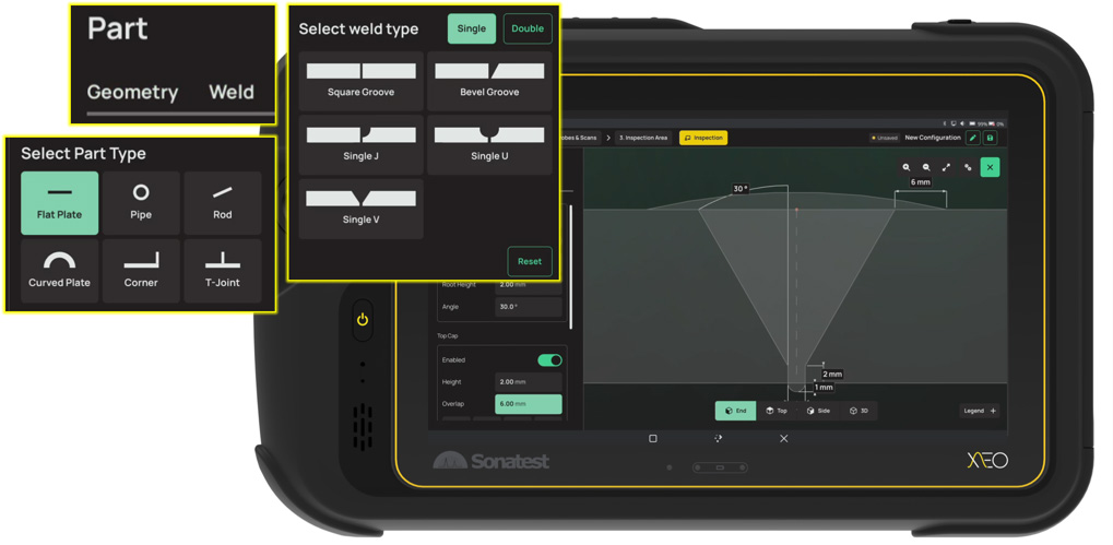
Figure 1 - Predefined part and weld categories for rapid profile creation.
The next step is to define the weld profile. The Weld menu provides the main weld categories, including single and double-sided weld configurations. These predefined profiles establish the overall weld geometry, after which the remaining dimensional parameters can be entered to match the actual component. For greater flexibility, the weld can also be flipped to align with the probe inspection face and support the chosen inspection strategy.
Figure 2 - Part Builder Overview
Once the part and weld geometry have been defined, probe positioning can be optimized. The probe location should always be verified to ensure the selected beam paths intersect the expected defect orientations. During setup, it is common to adjust the index offset to improve imaging quality, as the optimal inspection position may differ from the initial scan plan.
Component dimensions may also require adjustment during the inspection. Wall thickness can vary because of manufacturing tolerances, corrosion, or limited asset documentation. The XEO part builder makes these updates quick and straightforward, keeping the scan plan representative of the component being inspected.
Key Features of the XEO Part Builder
- Six base geometries and five weld types cover the most common inspection scenarios.
- Welds can be flipped to match the inspection surface, allowing practical scan planning regardless of the part orientation.
- Part dimensions and probe positioning can be updated quickly throughout the inspection process.
- Part geometries are fully compatible with PA, TFM, and TFMi™ imaging, and transmit and receive delay calculations automatically account for the component surface profile.
Conclusion
The XEO Part Builder gives inspectors CAD-like control to create accurate part and weld geometries with ease. When an unexpected profile appears during an inspection, users can quickly adjust part dimensions, refine weld features, and continue working with confidence. By combining simplicity with precision, Sonatest’s XEO makes it easier to manage even complex weld geometries.
Get in touch with your local Sonatest expert, available in more than 50 countries over 5 continents!
News Filter...
The latest news from Sonatest direct to your inbox.
Tags
- Phased Array
- Careers
- Exhibitions
- TFM
- CRFRP
- Composite Materials
- UT Testing
- WheelProbe 2
- Wave
- Software Update
- Transducers
- Education
- Weld Inspection
- Corrosion Mapping
- Ultrasonic Testing
- alphagage+
- Linear Scan
- Pipeline Integrity
- User Story
- Weldments Advanced UT
- metals
- Austentic steels
- Pipelines
- Storage Vessel
- Pressure Vessel
- Rail
- Boiler
- Flanges
- Nozzels
Related Products
