- Blog
A 360° Ultrasonic Inspection for Pipelines
The following blog contains many ultrasound solutions for pipelines. There are photos to bring up more context for each scenario.
What Solutions Can Ultrasound Provide for Pipelines?
This second blog in our pipeline series details the available ultrasonic inspection solutions for many pipeline region of interest and its safety-critical areas. The previous blog (A 101 Pipeline Integrity Guide for NDT Specialists) covered the general areas of interest where NDT should be applied when a routine check, failure analysis review, maintenance review or complete asset study is required. We also mentioned the extra difficulties surrounding specific pipeline regions of interest. This blog focuses on ultrasound techniques for which Sonatest provide inspection solutions for pipeline owners to utilise reliable and advanced ultrasound methods and equipment.
Ultrasound Covers Many Inspection Areas
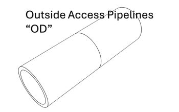
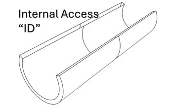
As with the previous blog, we will cover the two-outside diameter (OD) and inside diameter (ID) surface access situations where ultrasound is commonly employed. The blog will not cover all pipeline inspection cases, but most current technologies are included.
Note: Insulation on pipelines does not allow for the transmission of sound to the pipe below; this means for ultrasonic methods to be utilised, the insulation must be removed in the areas of interest. Alternatively, internal scanning methods such as pig crawlers can be used, or guided wave systems can be set at strategic points along the line, allowing for minimal insulation removal and screening of the pipe under the insulation.
General PA-UT Methods
The following section contains the OD scenario and the ID examinations. For each case (where applicable), there is an example of conventional UT, PA Inspection, TFM or even a corrosion map rendering for much better visualisation. BeamTool (Scan Plan) and CIVA Analysis (Sonatest Compatible Advanced Analysis software) were used to build this table below.
Corrosion Mapping
Conventional UT

0° Manual UT – Spot Reading Grid Method

0° Manual UT – 100% Manual Scanning Method of an Area
Corrosion Mapping
0° L-scan/TFM
 Scanning")
Manual Inspection (Not Encoded) Scanning

Example of a circumferential PA Scan corrosion survey that creates large C-scan data. This photo is a 128E WP2 scenario.

Automated/Semi-automated Scans: PA L-scan/UT/LL TFM Carried out with Crawler Scanners.
Constant Monitoring
Belt or Single Point
 Constantly Being Monitored on Pipelines (Can Be Positioned Under Insulation)")
Single/Multiple Point(s) Constantly Being Monitored on Pipelines (Can Be Positioned Under Insulation)
Elbow Mapping
Flex Probe, WheelProbe or Conventional UT

0° Manual UT – Spot Reading Grid
 Lens")
UT Automated Grid with Augmented Reality (AR) Lens

PA Using a Flexible or Wheel Probe Array
Flange Face Corrosion Inspection (Inner ROI)
In-service, Using Phased-Array
")
PA or TFM can be achieved around the flange. (Images and data courtesy of Ensonify)
A bolt can reduce the region of interest access. The inspection procedure is always challenging and amended accordingly because there are many flange profiles in the field.
Flange Inspection (Bolts)
Phased-Array

PA and/or TFM Bolt Scanning
New Infallible Option: Slim Bolt Scanner (By a Valve or 2 Side-by-side Flanges)

Our Wide Bolt Scanner Offer Depending on the Bolt Size Requirement and Height Clearance
Nozzle Inspection
Conventional UT

A-Scan with an Imported Nozzle Geometry for a Reliable Flaw and Geometry Echo Location
Nozzle Inspection
Phased-Array
")
Sectorial and/or Linear Scan with B-Scan and C-Scan (End and Top Scan Views)

PA inspection with folded S-scan and rotated around the nozzle
Butt Welds
Conventional UT and Phased Array

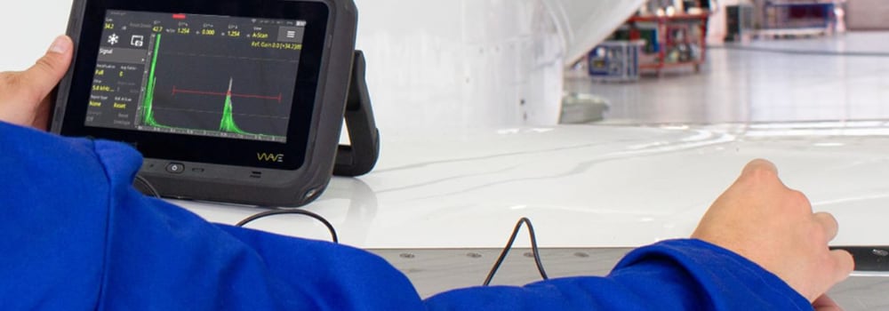
A-Scan with an Interactive Scan Plan; A Live A-scan Is Displayed in the Butt Weld Geometry
 in Parallel")
Sectorial and/or Linear Scan. This Ultrasound Solution Can Run Both the PA S-scan and TFMiTM (TT+TTT+TTTT) in Parallel
Special Cases
OD Surface Corrosion under Pipes Support

PA-CATTM - Remaining Wall of External Piping Assessment, Underneath Saddle Supports on Vessels – PA Pitch-catch S-scan with Post-analysis Profile Extraction
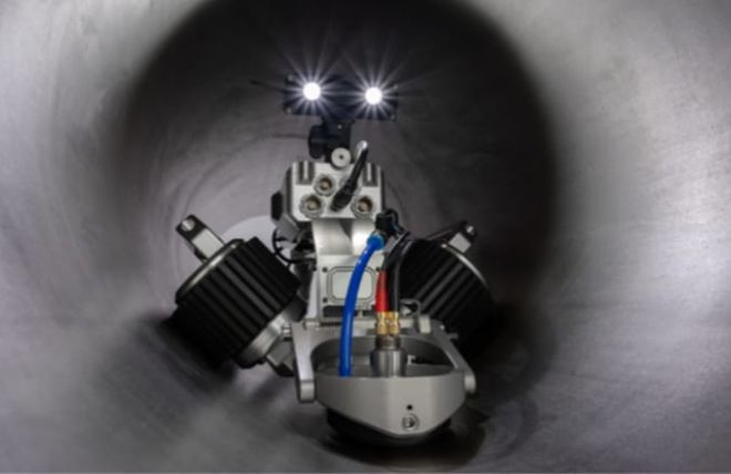
Internal Corrosion Mapping Inspection
UT or PA probe for medium/large diameters
")
Internal Scanners Better Suit Diameters Around 2 to 6 Inches. (TSIS Scanner)
For phased array inspections, we recommend a linear array and a motorised crawler like the following Jireh TERAX crawler.

Jireh TERAX crawler
Corrosion Mapping
Curved ID Linear Array

Special curved 19-inch AOD array design for ID inspection. Irrigation and encoder are included in that solution.
We would like to thank our partners to help us creating this blog content. All our partners are valuable to Sonatest and this is why we will order them in alphabetical order:
- BeamTool from Eclipse Scientific – Acuren
- Scan Plans
- Benor - Norway
- Danatronics
- Ensonify
- Flange Inspection Content
- EXTENDE CIVA Analysis
- Post Analysis Results
- JIREH inspection robotics
- Phoenix ISL
- Nozzle Scanner
- TSIS (Turbine Shaft Inspection System)
For more information please get in touch.
Please contact our Applications Team if you have any questions. You can also find more solutions on our website.
Stay up to date with our latest content. Sign up here to get our blogs delivered straight to your inbox.
News Filter...
The latest news from Sonatest direct to your inbox.
Tags