- Blog
Understanding Propagation Mode in Total Focusing Method (TFM)

12th May 2021
Marie-Pierre Despaux, Sonatest

The TFM technique is a new, emerging technique that is still misunderstood by many people today. A poor selection of propagation mode can seriously compromise the quality of the inspection.
What Is Propagation Mode in Total Focusing Method (TFM)?
The Total Focusing Method (TFM) technique involves reconstructing an image based on an A-scan matrix from the Full Matrix Capture (FMC). Everything is done using an algorithm. The latter must assume the sound path, the type of propagation wave and their respective speeds in order to reconstruct the image as it should. Incorrect parameterization or an inappropriate choice of propagation mode can cause distortion in the reconstructed image or an incorrect location of the defect.
The Challenges of Choosing the Right Propagation Mode
The TFM, compared to phased array ultrasonic testing (PAUT), has many advantages: better resolution (which makes it easier to distinguish two reflectors close to each other), a focused image at all points and increased sensitivity depending on the mode selected and the orientation of the defects. Therefore, if the propagation mode is not adequate with respect to the defect’s orientation, the amplitude response can greatly compromise its detectability, as demonstrated in Figure 1:

Figure 1: Typical representation of sensitivity as a function of the different propagation modes for image reconstruction. Multi-scan acquisition representing the PA- TT- TTT-TTTT views
The quality of the image reconstructed in TFM is based on the choice of the right propagation mode, the defect’s orientation and the instrument’s configuration such as the Zone of Interest (ZOI), speed and thickness. In other words, the propagation mode will not be the same if it is necessary to inspect a part suitable for delamination compared to a single V weld configuration.
How to Properly Choose the Propagation Mode
There are simulation software programs that can predict the amplitude response according to a defect’s orientation based on the propagation mode. The fact remains that the amplitude response of a defect as a function of a precise propagation mode remains easily predictive. In fact, a good understanding and knowledge of ultrasound physic enables an informed user to accurately predict their TFM inspection results.
Nevertheless, there are various TFM propagation modes that can be difficult for the inspection to rely on. Here are some tips for finding your way around:
- Identify the places likely to have discontinuities within the part inspected.
It is essential to know the relative position of the probe as a function of the ZOI. In fact, the sound path relative to the defect’s orientation will not be the same depending on the positioning of the probe. For example, there may be a mode that works very well for inspecting the left side of the weld but that is not suitable for the right side. - Identify the nature and likely orientation of the defects to be detected.
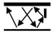
For example, during an angle inspection, the reconstruction algorithm for TT, TTT and TT-TT modes is predictive of the amplitude response as a function of a defect’s orientation. By relying on Figure 2, you can choose the appropriate mode according to the likely defect in the part.

Figure 2: The double, triple and quadruple modes will generally respond better to defects having a 45, 180 and 270-degree orientation, respectively
- Anticipate the level of ultrasonic energy depending on the defect’s location.
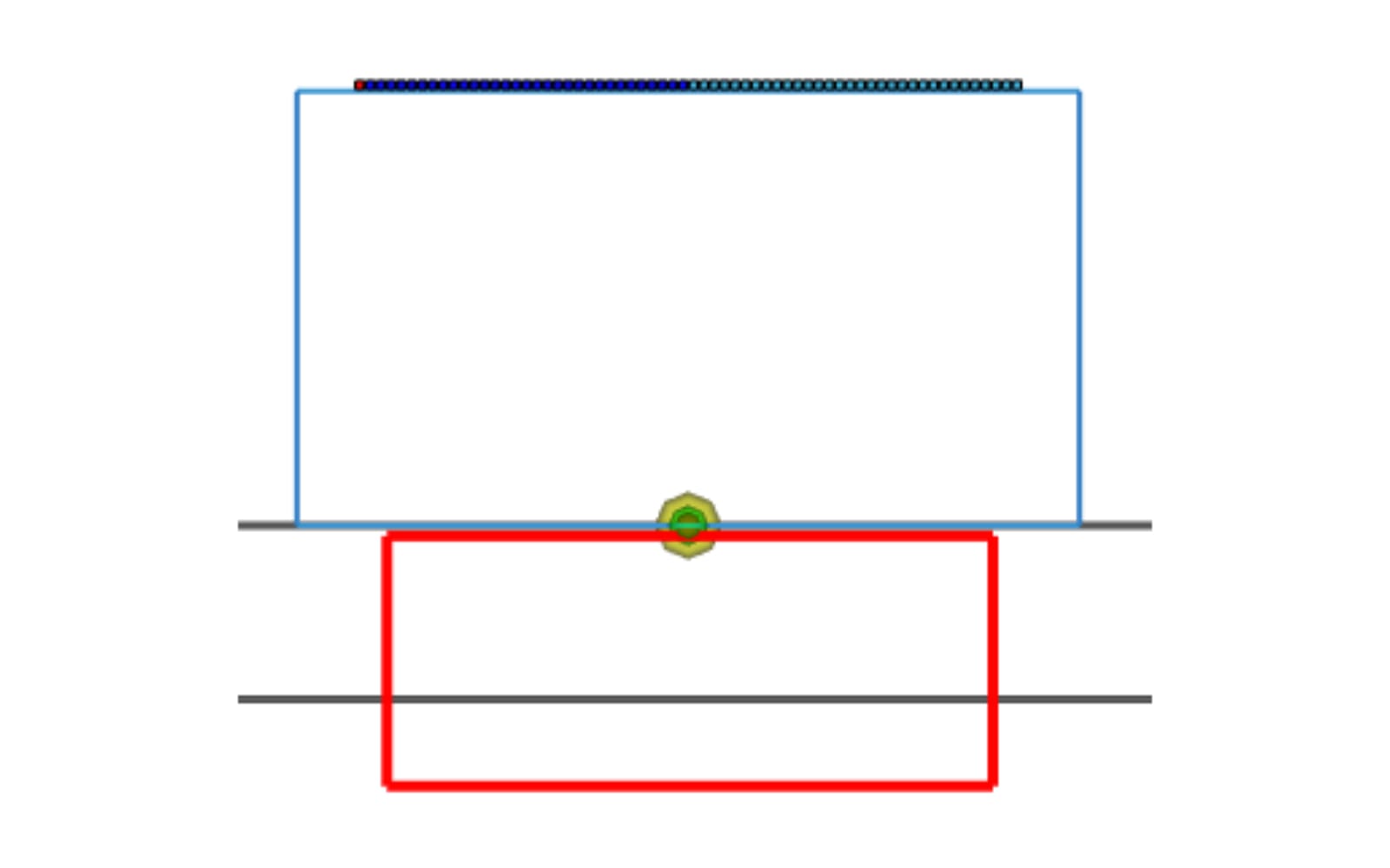
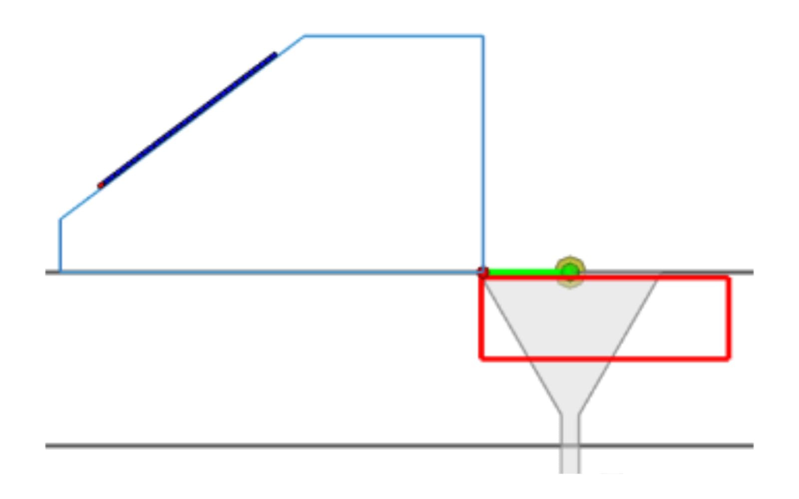
Like the response of a mode based on the defect’s orientation, the energy level of a given area relative to the probe is also predictive. Thus, it is easy to determine if a mode is more likely to detect a defect on the backwall or on the surface of the part. The following table provides concrete examples concerning the main propagation modes. The red rectangles represent the ZOIs.
| Sound Path | Modes | Recommended Location | Nature of Defect |
|---|---|---|---|
 |
LL |
For contact probes or flat wedges. It solves thickness reading applications underneath the probe volume. |
|
 |
|||
|
LL | For contact probes or flat wedges. It solves thickness reading applications underneath the probe volume. |
|
 |
|||
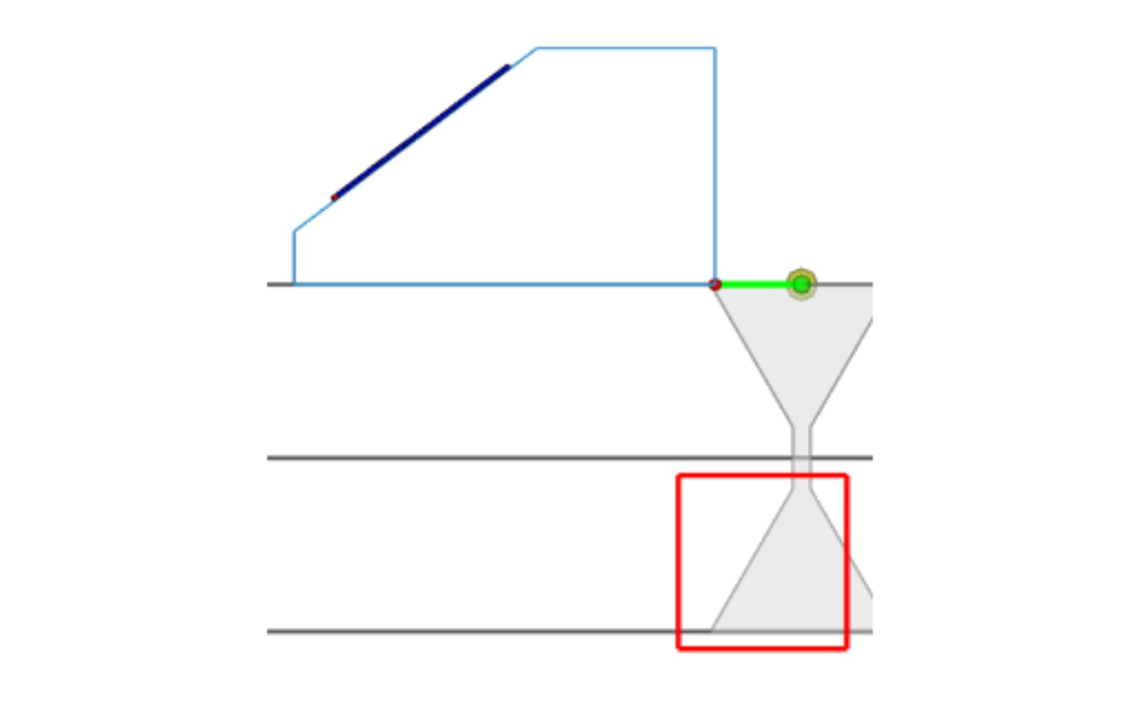
 |
LLT, TLT, TLL | Mostly energic for TLT mode. Mainly in the upper-middle. |
|
 |
|||
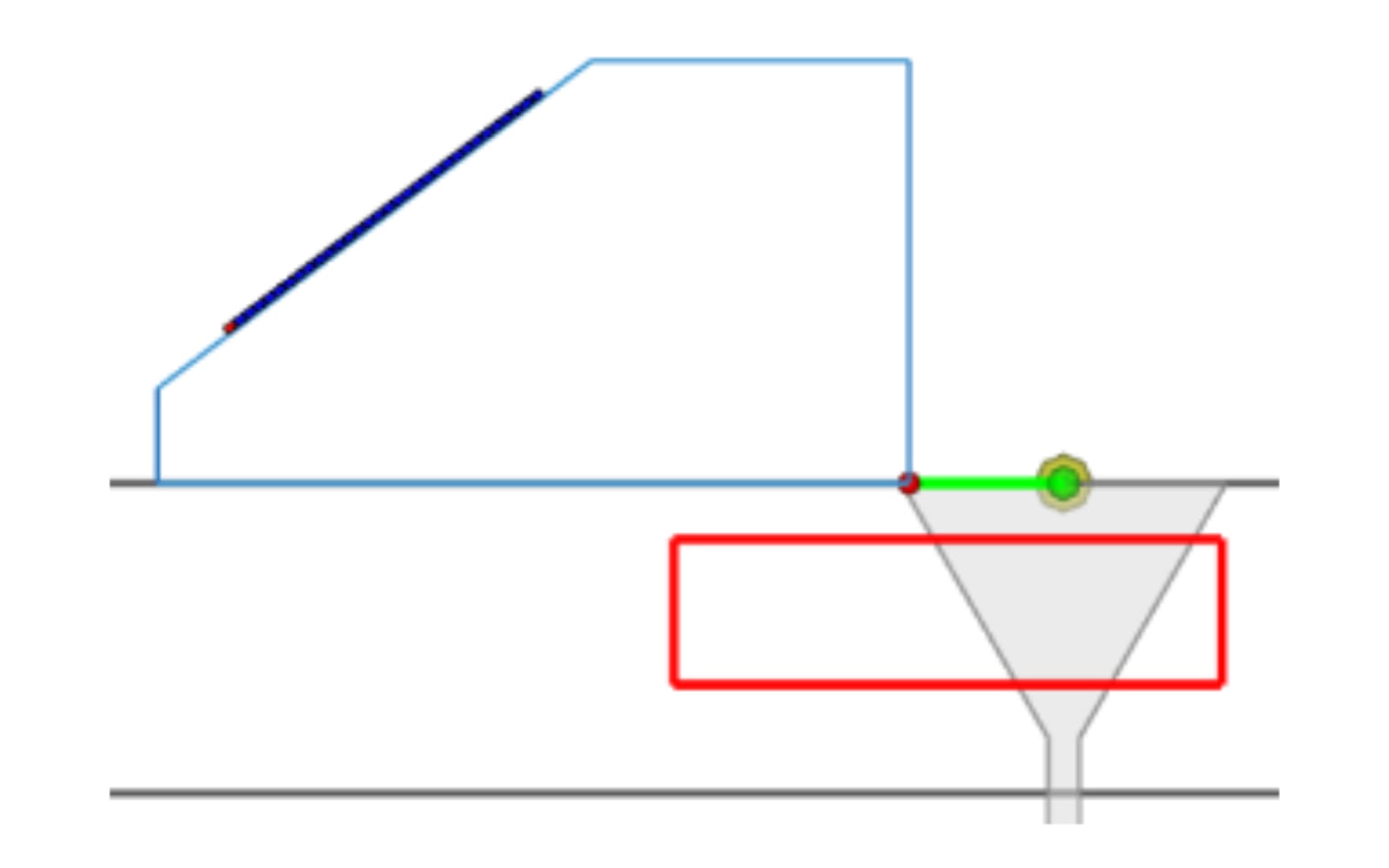
 |
TTT-TT | ZOI is located in the near surface zone, in the front of the wedge only. |
|
 |
|||
The standards committees are clear, integrating the TFM into the inspection procedures will require a rigorous qualification process in order to validate the accuracy of the assumptions or simulations!
The Veo3 combines several TFM modes simultaneously. Better still, the Veo3 can combine PAUT scans with TFM scans, and this capability provides the inspector an easier transition to imaging technology and enables them to base these results on a technology that they already master with the PAUT. This feature enables the user to build their expertise with confidence.
Please contact our Applications Team if you have any questions. You can also find more solutions on our website.
Stay up to date with our latest content. Sign up here to get our blogs delivered straight to your inbox.
News Filter...
The latest news from Sonatest direct to your inbox.
Tags