- Blog
Notches vs. Side-Drilled Holes Chapter 2 – Practical Effects
20th January 2022
Paul Holloway, President, Holloway NDT & Engineering Inc.
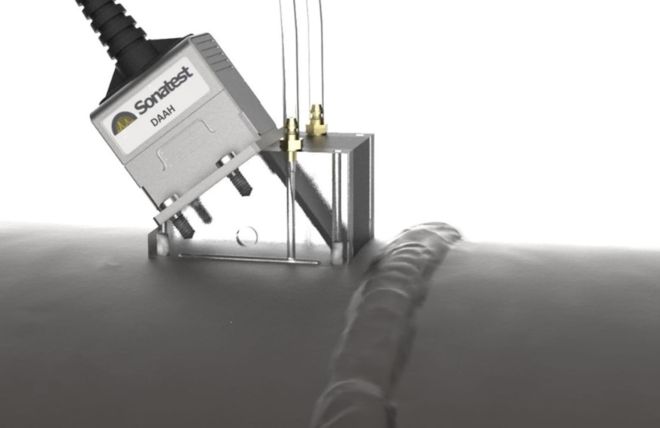
In Chapter 1, we highlighted the major differences in echo dynamics between side-drilled holes (SDHs) and notches. Notches are “big, loud and uneven”, while holes are “quiet and smooth”. In Chapter 2, we’ll take a look at the effect that each different calibration plays.
We Can Skip to the Practical Part
So, what are some practical differences between using notches vs. SDHs for calibration? So glad you asked!
Wedge delay: Hole yes, Notch no
Side-drilled holes can be used for wedge delay, but notches should not. For any depth-based wedge delay, you would normally enter in the target depth and move the probe so the target passes through all the angles in the sectorial view. With holes, the sound reflects at slightly different depths as the angle changes, but the error is negligible. A properly calibrated wedge delay on SDHs will produce a horizontal pattern as shown below on the left, all nicely lined up across the screen. But with notches, the sound reflects from the corner trap only until around 60 degrees, after which the mode conversion effects dominate and produce the "bump" seen below on the right.
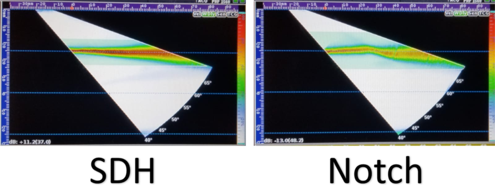
So, if you're using curved notch blocks and contoured wedges, plan ahead about how you're going to verify a wedge delay calibration.
Amplitude Effects
Here's another way to illustrate the differences between a TCG made with holes versus notches. Let's start by showing the result of a TCG using an SDH at a depth of 1 inch...
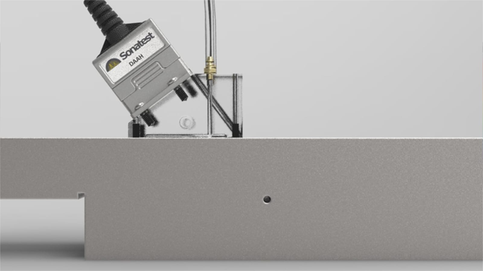
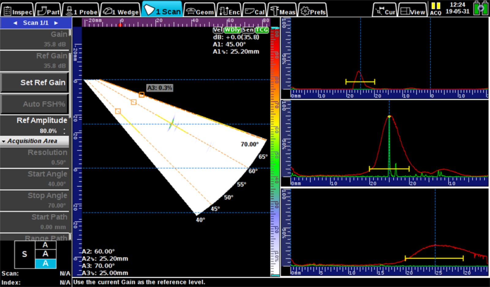
Below I've set up an S-A-A-A view where you can see the 45, 60 and 70 degree A-scans and the echo dynamics that the hole carves out at each one. No surprise, the response is 80% at all angles (because that's how a TCG works). This will be our baseline.
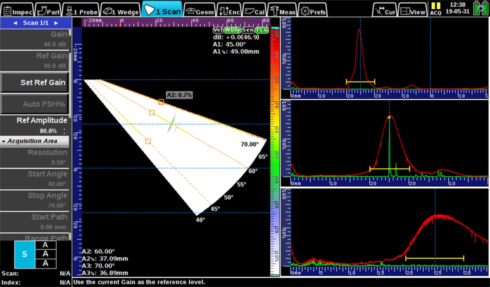
Next, we can redo the TCG using a notch and then rescan the same hole:
With a notch TCG, the mode conversion gives it that extra "boost" around 60 degrees which in this case brings the signal from the SDH back to about 80% (middle A-scan, below right). But at other angles like 45 and 70, the hole signal is much lower. This could cause problems if the defect you're looking for isn't exactly where you thought it was going to be.
In practice, you're not likely to encounter a perfectly vertical notch-like defect or a SDH in a weld. Cracks, surface breaking lack of fusion and lack of penetration on unbeveled edges have about as much chance as behaving exactly like machined notches as volumetric defects have of behaving like side-drilled holes.
Notches have some distinct advantages over holes: they are useful as surface breaking reference points and are the only viable option for thin-walled calibration standards. But for general weld examination, side-drilled holes provide a symmetric reference target without a preference for angle. And for most cases where holes could be used, they result in a more sensitive overall inspection. So the theory that "notches are better to find cracks" is simply not true in most cases.
Aside: The Blue Smear
Neat trick, if you turn the gain up on a calibration performed on notches, the S-scan should reveal a blue smear like this...
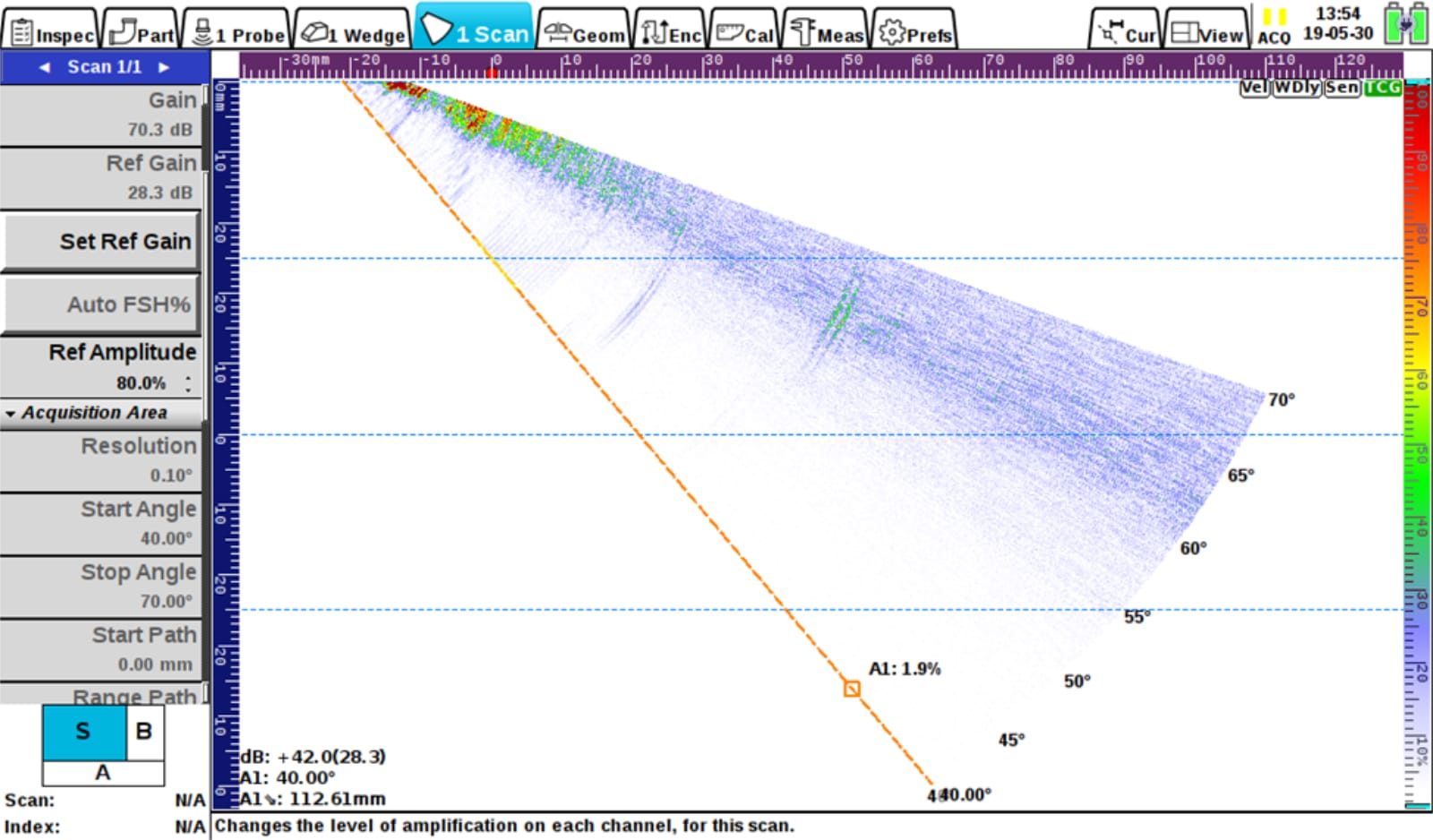
The blue smear is a sure-fire way to determine whether a calibration was performed on notches or SDHs, without even pulling out the calibration block. Keep in mind that right after calibration you probably won’t see the blue smear until you add a lot of scanning gain (I added a whopping 42dB here). Don’t take someone’s word for it, check it yourself!
Acknowledgements
Thanks to Colton Markowski (High Mountain Inspection - Wyoming) and Mathieu Magnan (Creaform - Quebec) for the awesome 3D model of the pipe and weld in the banner photo.
Please contact our Applications Team if you have any questions. You can also find more solutions on our website.
Stay up to date with our latest content. Sign up here to get our blogs delivered straight to your inbox.
News Filter...
The latest news from Sonatest direct to your inbox.
Tags