- Blog
Notches vs. Side-Drilled Holes Chapter 1 – Echo Dynamics

19th January 2022
Paul Holloway, President, Holloway NDT & Engineering Inc.

For ultrasonic testing of piping welds, ASME Sec V Art. 4 allows sensitivity calibration on notches using the standard block for piping (Fig. T-434.3-1) or side-drilled holes using the alternate block (Fig. T-434.3-2). They are both acceptable reference targets but behave quite differently due to a couple of super fun reasons.
Simple Comparison
For a comparison of echo-dynamics, simulation was performed with CIVA on a 20.5 mm curved block using both notch and side-drilled hole reflectors.
Multiple reflections of the hole were made, and intermediate data points interpolated to produce the same sound path as the notch (because you can't drill a hole at the ID, right?).
The chart below shows the results plotted against each other, with the loudest notch position (around 54°) set to 100% full screen height.
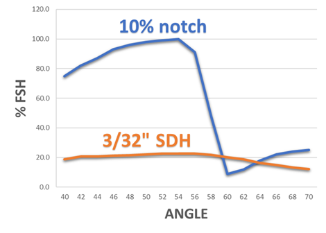
Well, would you look at that? Just look at that! Notches are really loud, aren’t they? And check out that dip at 60 degrees! Lets discuss why this happens…
Relative Size
For one, notches are relatively massive reflectors compared to side drilled holes, with sound reflecting primarily via the corner trap. Imagine playing pool and missing a corner pocket shot. You can miss by a little or a lot and the ball will still come back at you.
Side drilled holes are basically cylinders with sound reflecting off only the narrow strip perpendicular to the sound beam. Imagine the line of reflected light you’d see when shining a flashlight on a chromed cylinder rod. Side drilled holes are relatively small reflectors.
Symmetry
Meanwhile, side-drilled holes are symmetric reflectors, producing the same reflection profile at all angles with no mode conversion losses.

So what? What are you trying to get at?
A sensitivity calibration (e.g. DAC/TCG) created with notches will result in generally lower sensitivity than side-drilled holes. They are so loud that the gain must be turned way down in order to set the peak of the notches at 80% FSH. There is a 10 to 12 dB difference in the scenario shown in the chart above.
Caveat: Expect a smaller dB difference on thin wall calibration standards where the 10% notch is (obviously) smaller but the minimum ASME hole size (3/32 in. or 2.38 mm) remains the same.
In addition, a sensitivity calibration made on notches will produce very different amplitudes depending on angle. We already deal with this in UT anyways... the amplitude always changes depending on what angle you hit the flaw with (unless your weld flaw is a perfect cylinder or a sphere, which it probably isn't).
Please contact our Applications Team if you have any questions. You can also find more solutions on our website.
Stay up to date with our latest content. Sign up here to get our blogs delivered straight to your inbox.
News Filter...
The latest news from Sonatest direct to your inbox.
Tags